Table of Contents
Advertisement
Please refer to Corp1914-L8 for indoor and outdoor unit error codes and component diagnostics.
1. Indoor Units ................................................3
1.1.
Model Number Identification .....................................3
1.2.
Indoor Unit Specifications .........................................3
1.3.
Indoor Unit Dimensions ............................................4
1.4.
Indoor Unit Clearances .............................................4
1.5.
Indoor Unit Wall Mounts ...........................................5
1.6.
Indoor/Outdoor Matches ...........................................5
2. Air Throw Data ...........................................6
Systems .....................................................7
3.1.
Overview ...................................................................7
3.2.
Wire Gauge...............................................................7
3.3.
Terminal Connections ...............................................8
4. Indoor Unit Diagrams ................................8
5. Wireless Remote ........................................9
5.1.
Requirements ...........................................................9
5.2.
Remote Control Specifications .................................9
6.1.
with VRF Only) ........................................................ 11
6.2.
MWHA Wall Mount Single Zone
Air Conditioning Indoor Unit
Table of Contents
MINI-SPLIT SYSTEMS SERVICE MANUAL
MHA Series Unit Information
MHA Single Zone Air
Conditioning Outdoor Unit
Controller ................................................................12
6.3.
Dry Mode Operation - Indoor Units ......................... 12
6.3.1.
6.3.2.
6.4.
Test Run - Indoor Units ...........................................13
6.4.1.
6.4.2.
6.5.
Double-Check Pipe Connections ............................ 13
6.6.
Ambient Temperature is Below 63°F (17°C) ........... 13
7. Single Zone Outdoor Units .....................15
7.1.
Model Number Identification ...................................15
7.2.
Specifications..........................................................15
7.3.
Cooling and Heating Capacities .............................16
7.3.1.
7.3.2.
7.3.3.
7.3.4.
7.3.5.
7.3.6.
7.3.7.
7.3.8.
7.3.9.
7.3.10. Heating - 018 (208/230V) ......................... 21
7.3.11. Cooling - 024 (208/230V) .........................21
7.3.12. Heating - 024 (208/230V) ......................... 22
1
Procedure .................................................12
Dry Mode Operation Sequence ................ 13
Test Run Instructions ................................13
Before Test Run ........................................13
Cooling - 009 (115V) ................................16
Heating - 009 (115V) ................................17
Cooling - 009 (208/230V) .........................17
Heating - 009 (208/230V) ......................... 18
Cooling - 012 (115V) ................................18
Heating - 012 (115V) ................................19
Cooling - 012 (208/230V) .........................19
Heating - 012 (208/230V) ......................... 20
Cooling - 018 (208/230V) .........................20
CORP1913-L8
11/2020
Advertisement
Table of Contents

Related Manuals for Lennox MHA Series


Summary of Contents for Lennox MHA Series
-
Page 1: Table Of Contents
MINI-SPLIT SYSTEMS SERVICE MANUAL MHA Series Unit Information CORP1913-L8 11/2020 Please refer to Corp1914-L8 for indoor and outdoor unit error codes and component diagnostics. MWHA Wall Mount Single Zone Air Conditioning Indoor Unit MHA Single Zone Air Conditioning Outdoor Unit Table of Contents Controller ..............12... - Page 2 7.4. Unit Dimensions............22 17.1.5. Step Motor ..........42 7.5. Outdoor Unit Clearances ........23 17.1.6. Drain Hose ..........43 7.5.1. Single Units ..........23 17.2. Outdoor Unit ............43 7.5.2. Multiple Units ..........24 17.2.1. Panel Plate (Some Models)...... 43 17.2.2. Panel Plate (MWHA024S4) ...... 44 8. Refrigeration Pipe Work ......25 17.2.3. Electronic Components (MWHA009S4 and MWHA012S4) ........45 8.1. Single-Zone Refrigerant Cycle Diagram ....25 17.2.4. Electronic Components (MWHA018S4) ...
-
Page 3: Indoor Units
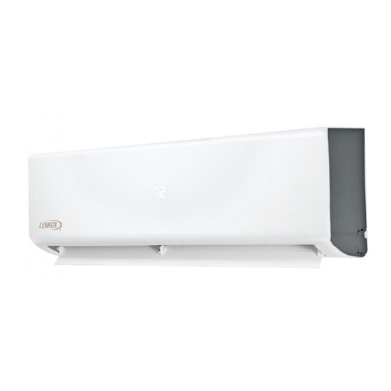
1. Indoor Units 1.1. Model Number Identification WALL-MOUNTED INDOOR UNITS M WH A 009 S 4 - 1 P Series Type Voltage M = Mini-Split L = 115V-1 phase-60Hz P = 208/230V-1 phase-60Hz Unit Type Minor Design Sequence WH = Wall-Mounted Non-Ducted Unit 1 = 1st Revision Major Design Sequence A = First Generation Refrigerant Type 4 = HFC-410A Nominal Cooling Capacity Cooling Efficiency 009 = 0.75 ton S = Standard Efficiency 012 = 1 ton 018 = 1.5 tons... -
Page 4: Indoor Unit Dimensions
1.3. Indoor Unit Dimensions TOP VIEW SIDE VIEW FRONT VIEW SIDE VIEW BOTTOM VIEW Figure 1. Indoor Unit Dimensions - Inches (mm) Size 29-5/8 11-3/8 8-5/8 32-3/4 11-3/4 8-3/4 39-1/8 12-1/2 9-7/8 1118 13-1/4 10-1/4 1.4. Indoor Unit Clearances Ceiling 6”... -
Page 5: Indoor Unit Wall Mounts
1.5. Indoor Unit Wall Mounts MWCA009S4 MWCA018S4 13-3/4 (349) 20-3/8 (518) 6-3/4 (171) 5-5/8 7 (178) 5-3/8 (137) (143) 5-3/8 (102) (136) 2-1/4 (57) 1-1/2 (38) Wall-Mount 2-1/4 Unit Outline Wall-Mount (57) Unit Outline 2-3/8 (60) 38 (965) 2 (51) Left Rear Hole Right Rear Hole 1-7/8... -
Page 6: Air Throw Data
2. Air Throw Data MWHA009S4 - COOLING MWHA009S4 - HEATING 8 ft. 9 in. 8 ft. 9 in. 0.3 ft./sec. 1.6 ft./sec. 1.6 ft./sec. 3.0 ft./sec. 3.2 ft./sec. 1.3 ft./sec. 3.0 ft./sec. 6 ft. 6 in. 6 ft. 6 in. 11.5 ft./sec. -
Page 7: Power And Communication Wiring For Systems
3. Power and Communication Wiring for See “Table 1. Single Zone Installation Wiring Requirements” and “Table 2. Specifications” on page 9 for wiring Systems requirements. CAUTION 3.2. Wire Gauge This unit must be properly grounded and protected by a circuit breaker. The ground wire for the unit must not be Table 1. -
Page 8: Terminal Connections
3.3. Terminal Connections 115VAC Indoor Unit 208/230V Indoor Unit Terminal Block 115VAC Outdoor Unit Terminal Block 208/230V Outdoor Unit Terminal Block Terminal Block From Power From Power Suppl y Suppl y 18 and 24K unit has five terminal sets. Outdoor Unit Indoor Unit Outdoor Unit Indoor Unit... -
Page 9: Wireless Remote
5. Wireless Remote Mode button. Press to scroll through the operation • modes: IMPORTANT! Auto → Cool → Dry → Heat → Fan. • Fan speed. Press to scroll through the fan speeds: Frequent changes to operating mode may cause system malfunction. Allow at least one minute between mode Auto → Low → Med → High. changes for the system to stabilize. • Sleep button. Press to activate “night-mode”. This will automatically increase (cooling) or decrease (heating) 5.1. Requirements the setpoint 2°F (1°C) increment per hour for the first Using the remote controller two hours. The modified setpoint will be set for five hours. After seven total hours the indoor unit will turn • Point the remote controller directly at the indoor unit. off. • Stand within 26 feet (8 meters) of the indoor unit. NOTE: SLEEP mode is only available when the unit is in •... - Page 10 • Timer ON button. Press to set the number of hours of the operation modes: delay before the indoor unit begins operation. Auto → Cool → Dry → Heat → Fan. • Timer OFF button. Press to set the number of hours of • Setpoint or Room Temperature. Displays the setpoint delay before the indoor unit stops operation. temperature during normal operation. Displays the room temperature when in Follow me mode. Adjust • Swing button. Press once to initiate louver up and the setpoint with up & down arrow buttons. No display down oscillation. Press again to stop louver oscillation. when unit is in Fan mode. Louvers remain in place where stopped. Not available in all indoor unit models. • Remote controller On. Icon displays to indicate that the remote controller is on. • Direct (Direction) button. Press to move louvers up and down in 6 degree increments. Louvers remain in • Transmitting display. Icon blinks once when a signal place where stopped. is sent from the wireless remote controller.
-
Page 11: Connection To Centralized Controller
indoor unit at selected intervals. WARNING Timer ON Operation 1. Press the Timer ON button. The Timer ON icon, the last Do not mix old and new batteries or batteries of different auto-on time, and “h” will display. types. 2. Press the Timer ON button again to set the amount of Do not leave the batteries in the remote controller if the time before the indoor unit begins operation. Each press controller will not be used for an extended amount of time. will increase the time in half hour increments until 10 Dispose of used batteries following local and state waste hours, then the increment becomes 1 hour. management standards. Timer OFF Operation Select Fahrenheit or Celsius 1. -
Page 12: Indoor Unit Connection Points For Centralized
Switch location and color varies for each indoor unit. Two examples are shown above. Figure 12. Dip Switch Settings 6.2. Indoor Unit Connection Points for Centralized Controller Mini-split indoor units can be connected to a centralized controller (e.g. Lennox VRF Manager - LVM or Trane Tracer) or a BACnet or LonWorks gateway using the XYE terminals on the indoor unit main board. Figure 14. Typical Indoor Unit Connection Points 6.3. Dry Mode Operation - Indoor Units 6.3.1. -
Page 13: Dry Mode Operation Sequence
not operate in this mode. The Follow Me mode is Water drains properly from only available when a return air sensor is utilized. drain hose Typically in most cases the Follow Me mode will All piping is properly not be sufficient to remove excessive humidity. insulated NOTE: In addition, the outdoor units do not have a Unit performs COOL humidistat installed therefore they are unable to... - Page 14 Manual control button Figure 15. Manual Button Location...
-
Page 15: Single Zone Outdoor Units
7. Single Zone Outdoor Units NOTE: Outdoor units can only be installed in an unenclosed outdoor environment. 7.1. Model Number Identification M H A 009 S 4 S - 1 P Series Type Voltage M = Mini-Split L = 115V-1 phase-60Hz P = 208/230V-1 phase-60Hz Minor Design Sequence Unit Type 1 = 1st Revision H = Heat Pumpr Refrigerant Circuits S = Single Circuit Major Design Sequence... -
Page 16: Cooling And Heating Capacities
Design Pressure PSIG 550 / 340 550 / 340 550 / 340 550 / 340 Shipping Net/Shipping weight (lbs.) (115V) 67 / 72 71 / 77 - - - - - - Data (208/230V) 67 / 72 67 / 73 80 / 86 106 / 113 ELECTRICAL DATA Electrical Characteristics - 60 Hz - 1 Phase 115V 208/230V... -
Page 17: Heating - 009 (115V)
7.3.2. Heating - 009 (115V) Outdoor Indoor Temperature - °F (Dry Bulb) Temperature - °F 60°F 65°F 70°F 75°F (Dry Bulb) Total Total Total Total mBtuh mBtuh mBtuh mBtuh –13 4.49 4.34 4.11 3.94 –5 5.45 5.30 5.01 4.83 6.20 6.01 5.69 5.46... -
Page 18: Heating - 009 (208/230V)
7.3.4. Heating - 009 (208/230V) Outdoor Indoor Temperature - °F (Dry Bulb) Temperature - °F 60°F 65°F 70°F 75°F (Dry Bulb) Total Total Total Total mBtuh mBtuh mBtuh mBtuh –13 5.86 5.67 5.37 5.12 –5 6.98 6.75 6.39 6.10 8.10 7.84 7.41 7.11... -
Page 19: Heating - 012 (115V)
7.3.6. Heating - 012 (115V) Outdoor Indoor Temperature - °F (Dry Bulb) Temperature - °F 60°F 65°F 70°F 75°F (Dry Bulb) Total Total Total Total mBtuh mBtuh mBtuh mBtuh –13 4.66 4.51 4.24 4.07 –5 5.56 5.38 5.05 4.87 6.41 6.21 5.82 5.59... -
Page 20: Heating - 012 (208/230V)
7.3.8. Heating - 012 (208/230V) Outdoor Indoor Temperature - °F (Dry Bulb) Temperature - °F 60°F 65°F 70°F 75°F (Dry Bulb) Total Total Total Total mBtuh mBtuh mBtuh mBtuh –13 5.93 5.69 5.45 5.24 –5 7.06 6.78 6.49 6.27 7.86 7.54 7.21 6.89... -
Page 21: Heating - 018 (208/230V)
7.3.10. Heating - 018 (208/230V) Outdoor Indoor Temperature - °F (Dry Bulb) Temperature - °F 60°F 65°F 70°F 75°F (Dry Bulb) Total Total Total Total mBtuh mBtuh mBtuh mBtuh –13 6.96 6.69 6.46 6.27 –5 8.30 7.97 7.69 7.38 9.23 8.82 8.55 8.25... -
Page 22: Heating - 024 (208/230V)
7.3.12. Heating - 024 (208/230V) Outdoor Indoor Temperature - °F (Dry Bulb) Temperature - °F 60°F 65°F 70°F 75°F (Dry Bulb) Total Total Total Total mBtuh mBtuh mBtuh mBtuh –13 12.34 11.86 11.47 11.07 –5 14.70 14.13 13.65 13.04 16.35 15.71 15.17 14.48... -
Page 23: Outdoor Unit Clearances
MCA024S4S 33-5/8 (854) 27-5/8 (702) 7-7/8 21-1/4 (540) 14-1/4 (362) (13) (200) 33-1/4 (845) SIDE VIEW 2-3/4 FRONT VIEW (70) 1-3/8 (35) 13-1/8 13-3/4 (333) (349) (381) BOTTOM VIEW 2-3/8 (60) 3-5/8 (92) SIDE VIEW Figure 17. 24K Outdoor Unit Dimensions - Inches (mm) 7.5. -
Page 24: Multiple Units
7.5.2. Multiple Units Height of Wall (C) NOTE: It is recommended that the single clearance be followed in a multi-unit applications. If not then these are the maximum and minimum clearances Unit you are allowed. Height (A) CLEARANCE NOTES FOR MULTIPLE UNITS: If the height of the wall (C) is less than or equal to the height of the smallest unit (A), the distance from the unit to the wall (B) must be a minimum of 10 inches (254 mm). -
Page 25: Refrigeration Pipe Work
8. Refrigeration Pipe Work 8.1. Single-Zone Refrigerant Cycle Diagram CHECK VALVE LIQUID SIDE (Heating Model only) 2-WAY VALVE CAPILIARY TUBE HEAT HEAT EXCHANGE EXCHANGE (EVAPORATOR) (CONDENSER) T1 Room temp. sensor T2 Evaporator temp. sensor GAS SIDE 4-WAY VALVE 3-WAY VALVE ACCUMULATOR COOLING COMPRESSOR... -
Page 26: Outdoor Unit Connections And Line Set Usage
Table 4. Line Set Guide Each system size has a line set length and vertical elevation parameters. Maximum Line Set Diameters (in.) Maximum Elevation Elevation Maximum Line System Outdoor Unit BELOW Additional Refrigerant for greater Outdoor Unit Set Length - Size (KBtu) Indoor Unit - Feet than 25 Foot Line Set Lenght ABOVE Indoor Feet (Meters) Liquid... -
Page 27: Power And Communication Wiring For Systems
10. Power and Communication Wiring for Systems CAUTION This unit must be properly grounded and protected by a circuit breaker. The ground wire for the unit must not be connected to a gas or water pipe, a lightning conductor or a telephone ground wire. Do not connect power wires to the outdoor unit un- til all other wiring and piping connections have been completed. -
Page 28: Outdoor Unit Diagrams
11. Outdoor Unit Diagrams BLACK REAC TOR L N Y/G CN 3CN 1CN 2CN 16 CN 1A OUTDOOR CONTROL BLUE 4-WAY CN 30 CN 29 CN 28 BLACK CN 50 CRANKCASE HEATER HEATER CN 21 CN 7 DC- FAN T3 T4 Figure 20. -
Page 29: Installation Requirements
BLACK BLUE BLUE BROWN CN 1A OUTDOOR CONTROL BLUE 4-WAY VALVE BLACK CRANKCASE HEATER COMPRESSOR HEATER CN 21 CN 7 OU TDOOR FA N T5 T3 T4 Figure 22. 09K, 12K and 18K - 208/230VAC Outdoor Unit Wiring Diagram BLACK 3 BLUE L1L2 CN 6 CN 7 CN 8 CN 2... -
Page 30: Gas Leak Check With Soap Water
12.1. Gas Leak Check with Soap Water: 12.4. Adding Refrigerant if Pipe Length Exceeds Charge Less Pipe Length Apply soap water or a liquid neutral detergent on the connections with a soft brush to check for leakage in the pipe Connect the charge hose to the charging cylinder and open the two-way and three-way valves. With the charge hose connecting points. If bubbles emerge, the pipes are leaking. you disconnected from the vacuum pump, connect it to the valve at the bottom of the cylinder. -
Page 31: Servicing Indoor Unit Refrigeration Circuit
• Be sure to check for gas leaks. • Turn the flare nut of the three-way valves about 45° counterclockwise for six or seven seconds after the gas 12.6. Servicing Indoor Unit Refrigeration coming out, then tighten the flare nut again. Make sure Circuit the pressure display in the pressure indicator is a little higher than the atmosphere pressure. Then remove the 12.6.1. Collecting Refrigerant into Outdoor Unit charge hose from the three-way valve. • Confirm that both the two-way and three-way valves • Fully open the two-way valve and three-way valve and are set to the opened position securely tighten the cap of the three-way • Remove the valve stem caps and confirm that the valve 12.7. Evacuation after Servicing the Outdoor stems are in the opened position. Unit Refrigeration Circuit • Be sure to use a hexagonal wrench to operate the valve stems. -
Page 32: Electronic Function
while operating the air conditioner, turn off the air conditioner before disconnecting the hose. • Mounted the valve stem caps and the service port. Use torque wrench to tighten the service port cap to a torque of 18N·m (13.27 ft·lbs). • Always leak check after servicing the refrigerant system. There are one low-pressure centralized valve and one high- pressure centralized valve, it will be more time saving when vacuum and recycle refrigerant. But refer to the previous instruction when vacuum and recycle refrigerant. 13. Electronic Function 13.1. Abbreviation Figure 24. Typical Location of Outdoor Unit LEDs • T1: Indoor ambient temperature • T2: Middle indoor heat exchanger coil temperature • T3: Outdoor heat exchanger pipe temperature •... -
Page 33: Specifications And Operations
16. Specifications and Operations Table 7. Electronic Functions Abbreviations Indoor ambient temperature Coil temperature of indoor heat exchanger Pipe temperature of outdoor heat exchanger Outdoor ambient temperature Compressor discharge temperature Table 8. Electronic Control Working Environment Input voltage: 230V Input power frequency: 60Hz Indoor fan normal working amp. is less than 1A Outdoor fan normal working amp is less than 1.5A Four-way valve normal working amp is less than 1A Table 9. Main Protection Three minutes delay at restart for compressor One minute delay for the first time start-up and three minutes delay for others Temperature protection of compressor discharge When the compressor discharge is getting higher, the running frequency will be limited as below rules: If 215.6°F (102°C) < T5 < 244.4°F (115°C), decrease the frequency to the lower level every two minutes until to F1. If T5 < 244.4°F (115°C) for ten seconds, the compressor will stop and restart till T5 < 194°F (90°C) Table 10. Indoor/Outdoor Units Communication Protection If the indoor units cannot receive the feedback signal from the outdoor units for two minutes, the unit will stop and display failure. When T3>149°F (65°C) for three seconds, the compressor will stop while the indoor fan and outdoor fan will continue. -
Page 34: Cooling Chart
16.1. Cooling Chart Table 11. Cooling - Fahrenheit (Celsius) °F(°C) ODU(DB) IDU(DB/WB) (-17) (-15) (9.44) (7.22) (23.89) (29.44) (35) (40.56) (46.11) (48.89) 70/59 (21.11/15) 75/63 (23.89/17.22) 80/67 (26.67/19.44) 90/73 (32.22/22.78) 16.2. Heating Chart Table 12. Heating - Fahrenheit (Celsius) °F(°C) ODT / IDT 57/53 47/43 37/33... -
Page 35: Capacity Request Calculations
16.3. Capacity Request Calculations Total capacity Request=Σ(Norm code × HP) /10× modify rate+ correction. T1 Ts Figure 25. Cooling Mode Capacity Area Norm Code (N) NOTE: The final result is integer. Plus all the indoor capacity request together, then modify it by T4. When there is only one indoor unit: Outdoor Temperature (T4) >29°C 18°C to 29°C <17°C Cooling >84.2°F 64.4°F to 84.2°F <62.6°F Modify Rate 100% When there is more than one indoor unit: Outdoor Temperature (T4) >25°C 17°C - 25°C <17°C Cooling >77°F 62.6°F - 77°F <62.6°F Modify Rate 100% NOTE:... -
Page 36: Outdoor Fan Control
16.4. Outdoor Fan Control 16.4.1. Cooling Mode Normally the system will choose the running fan speed according to ambient temperature: DC_FAN_HI_SPD_ADD 28℃ 26℃ DC_FAN_MID_SPD_ADD 25℃ 23℃ DC_FAN_MIN_SPD_ADD 22℃ 20℃ DC_FAN_SLOW_SPD_ADD 19℃ 17℃ DC_FAN_SSLOW_SPD_ADD When low ambient cooling is valid: High low ambient cooling Outdoor fan speed control logical (low ambient cooling). When T4 <15°C (59°F) and T3 < 30°C (86°F), the unit will enter into low ambient cooling mode. The outdoor fan will choose speed according to T3. When T3≥38°C (100.4°F) or when T4≥20°C (68°F), the outdoor fan will choose the speed according to T4 again. Exit low ambient cooling mode run with high fan for 1 minute... -
Page 37: Indoor And Outdoor Unit Disassembly
17. Indoor and Outdoor Unit Disassembly NOTE: This section is for reference only. Actual unit appearance may vary. 17.1. Indoor Unit (All Models) 17.1.1. Front Panel Step 1. Hold the front panel by the tabs on the both sides and lift it. Horizontal Louver Hook Step 4. Bend the horizontal louver lightly by both hands to loosen the hooks, then remove the horizontal louver. Step 2. Push up the bottom of an air filter (step 1), and then pull it out downwards (step 2). - Page 38 Step 9. Release the hooks with hands. Step 6. Disconnect the connector for display board. Step 7. Slide the front panel side to side to release each axis. Step 8. Open the screw cap and then remove the three screws.
-
Page 39: Electrical Parts
Step 10. Release the five hooks in the back. Hooks 17.1.2. Electrical Parts NOTE: When handling electrical parts use anti-static Step 11. Pull out the panel frame while pushing the hook gloves. through a clearance between the panel frame and the heat exchanger. NOTE: Remove the front panel (see Step 1 on page 37) before disassembling electrical parts. Step 1. Cut the ribbon by a shear, then pull out the coil temperature sensor (T2). Step 2. Remove one fixing screw of the electronic control box and two screws used for the ground connection. - Page 40 Step 6. Open the left side plate of electronic control box. Step 7. Open the two clips on the front of the electric box. Step 4. Remove the fixed devices of the connectors. Step 8. Open the upper cover plate of electronic control box. Step 5. Disconnect the connectors of fan motor, the step motor and the T2 sensor. Step 9. Remove 1 screw and open the 2 clips along the direction indicated in image below.
-
Page 41: Evaporator
Pipe Header Step 2. Remove the one screw on the evaporator located at the fixed plate. Step 10. Pull out the electrical main board along the direction indicated in right image to remove it. Terminal S Display Board Screw RoomTemp Sensor Terminal 1L Terminal W Pipe Temp Sensor 17.1.3. Evaporator NOTE: Remove the front panel and electrical parts (see both “Front Panel” on page 37 and “Electrical Parts”... -
Page 42: Fan Motor And Fan
Step 3. Release the hook on the evaporator. on page 39 Electrical parts and “17.1.3. Evaporator” on page 41) before disassembling fan motor and fan. Step 1. Remove the two screws and remove the fixing board of the fan motor. Screws Step 4. Remove the one screw on the evaporator located oat the fixed plate. Step 2. Remove the bearing sleeve. Step 5. Pull out the evaporator. Step 3. Remove the fixing screw. Step 4. Pull out the fan motor and fan assembly from the side. -
Page 43: Drain Hose
17.2. Outdoor Unit Parts” on page 39 Electrical parts) before disassembling step motor. 17.2.1. Panel Plate (Some Models) Step 1. Remove the two screws, then remove the stepping motor. Step 1. Turn off the air conditioner and the power breaker. Step 2. Remove the screw of the big handle and then remove the handle. Stepping Motor 17.1.6. Drain Hose Step 1. Rotate the fixed wire clockwise indicated in imagine below. Step 3. Remove the screws of the top cover and then remove top cover. One of the screws is located underneath the big handle. -
Page 44: Panel Plate (Mwha024S4)
Step 4. Step 7. Remove the screws of the front panel and then Remove the screws from the right panel and then remove the front panel. remove panel. Front Panel Step 5. Remove the screw from the water collector cover. Right Panel 17.2.2. Panel Plate (MWHA024S4) Step 1. Turn off the air conditioner and the power breaker. Water Collection Cover Step 2. Remove the screws that secure the handle and then remove the handle. Step 6. Remove the screws on the rear coil guard and then remove the coil guard. Front Cover Step 3. Remove the screws from the top cover and then remove. One of the screws is located underneath the handle. -
Page 45: Electronic Components (Mwha009S4 And Mwha012S4)
Top Cover Front Cover Step 4. Remove the screws from the front panel and then remove panel. 17.2.3. Electronic Components (MWHA009S4 MWHA012S4) Front Panel NOTE: Antistatic gloves must be worn when you dissemble the electronic box. NOTE: Remove the panel plate before disassembly the fan. Step 1. Remove the connector for the compressor. Step 2. Pull out the two blue wires connected to the Step 5. -
Page 46: Electronic Components (Mwha018S4)
17.2.4. Electronic Components (MWHA018S4) Step 1. Remove the connector for the compressor. 4-way valve Step 2. Pull out connectors for the condenser coil temperature sensor (T3), outdoor ambient Reactor temperature sensor (T4) and discharge temperature sensor (TP). Step 3. Disconnect the four-way valve wire. Step 4. Disconnect the ground wire. Step 5. Remove the connector for the indoor unit. Step 6. Remove electronic control box. Fan Motor Compressor T3, T4 and TP 17.2.6. Fan Disassembly (MWHA009S4 MWHA012S4) NOTE: Antistatic gloves must be worn when you dissemble the electronic box. -
Page 47: Fan Disassembly (Mwha018S4)
Step 5. Remove the screws securing the fan motor and then remove fan assembly. Fan Motor Step 3. Release the hooks and then open the electronic control box cover. 17.2.7. Fan Disassembly (MWHA018S4) Step 1. Remove the nut security the fan to the fan motor. Hook Step 2. Remove the screws securing the cover of the electronic control box cover. Step 4. Disconnect the connector from the fan motor from the electronic control board. Step 3. Disconnect connector from electronic control board plug. Fan Motor Connector... -
Page 48: Fan Disassembly (Mwha024S4)
Step 3. Disconnect the connector for the fan motor from the electronic control board. Fan Motor Connector Step 4. Remove the screws securing the fan motor to Step 4. Remove the screws securing the fan motor from body. Then remove fan motor. body. Remove the fan. 17.2.8. Fan Disassembly (MWHA024S4) Step 1. Remove the nut security the fan with a spanner. Then remove the fan. Fan Motor D Cut Step 2. Release the hooks and then open the electronic control box cover. Hook... -
Page 49: Sound Blanket
17.2.9. Sound Blanket 17.2.11. Compressor NOTE: Recover refrigerant before removing NOTE: Recover refrigerant before removing compressor. compressor. Step 1. Remove the flange nut of the terminal cover and remove the cover. Sound Blanket Sound Blanket (side) Terminal Cover 17.2.10. Four-Way Valve WARNING: Recover refrigerant from the refrigerant circuit before remove the four-way valve. NOTE: Remove the panel plate, electrical parts, and fan assembly before disassembling four-way valve. - Page 50 Step 4. Heat up the brazed parts and then remove the discharge and suctions pipes. Step 5. Lift the compressor from the base pan assembly with pliers.
Need help?
Do you have a question about the MHA Series and is the answer not in the manual?
Questions and answers
Fan runs all the time when in auto
The Lennox MHA Series fan may run continuously when set to auto due to its low ambient cooling mode. In this mode, if the outdoor temperature (T4) is below 15°C and the coil temperature (T3) is below 30°C, the unit enters low ambient cooling, and the fan speed is controlled based on T3. If T3 rises to 38°C or T4 reaches 20°C, the fan speed is controlled by T4 again. This automatic adjustment can cause the fan to run continuously to maintain cooling performance in varying ambient conditions.
This answer is automatically generated