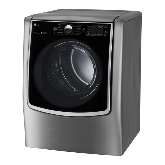
Page 1
Service Manual is STRICTLY PROHIBITED unless you have obtained the prior written consent of the LG Electronics entity from which you received this Service Manual. The material covered by this prohibition includes, without limitation, any text, graphics or logos in this Service Manual.
3-1. Connecting Electric Dryers 4-wire direct If this type is available at your home. you will be connecting to a fused disconnect or circuit breaker 3-wire direct 5" (12.7 cm) If this type is available at your home. you will be connecting to a fused disconnect or circuit breaker...
Page 11
Mid High 10min Steam Fresh™ Adjustable Adjustable Steam High 31min Sanitary™ Antibacterial High NORMAL Bedding Medium NORMAL Heavy Duty High NORMAL Perm.Press 32min NORMAL Normal Medium 41min NORMAL Delicates 28min NORMAL Mid High Towels NORMAL Jumbo Dry Medium 85min 45˚C NORMAL High 50min...
Page 12
Auto reset -31°F (-35°C) Same shape as outlet thermostat. 4. LED Lamp Schematic: If the lamp is turned on It is not by connecting is normal. measured by multimeter because V is 3.2V Measure resistance of the following terminal 1) Door open Terminal: COM - NC (1-3) Terminal: COM - NO (1-2) 2) Door closed...
Page 14
Ω Ω Electric type 15. Inlet. valve Measure resistance of the Following terminal Left picture -.plate...
Page 15
When checking Component, be sure to turn Power off, then do voltage discharge sufficiently. Ω Ω Ω Ω...
Page 18
TurboSteam™ helps prevent the overdrying of clothes by injecting steam during the drying process. The Steam Shield Function extends the life of clothes.
Page 20
Thermistor of blower • tE1 error is displayed in the Outlet thermistor open or shorted. housing drying cycle or test mode. Thermistor of blower • tE2 error is displayed in the Outlet thermistor open or shorted. housing drying cycle or test mode. •...
9-2 Installation Test (Duct Check) Once you have completed the installation of the dryer, During the two minute test cycle, monitor the FLOW use this test to make sure the condition of the exhaust SENSE display on the control panel. If the Flow system is adequate for proper operation of the dryer.
Page 23
• Check the Error Code before you call for service Error Code Possible Causes Solutions or tE2 • Temperature sensor failure • • Humidity Sensor failure. • • Electric dryer power cord is not • Check the power supply or the connection of connected correctly, or house power power cord to the terminal block.
Page 24
L06(Elec Type) L07(Gas Type) Main PGM Display PGM Thermistor open Thermistor shorted 180 in normal condition. ELECTRIC TYPE Mist Valve on, Motor+ Heater1+Heater2 off Water Supply Valve Mist Valve GAS TYPE Mist Valve on, Motor+ Gas Valve off Loads off Water Level Sensor...
Test 8 Motor Assembly, DC, Pump Before measuring resistance, be sure to turn power off, and do voltage discharge. Caution (When discharging, contact the metal plug of power cord with the ground wire.) Trouble Symptom During the diagnostic test, E5 error occurs. Measurement Condition Turn the dryer’s power off, then measure resistance.
CHANGE GAS SETTING (NATURAL GAS, PROPANE GAS) Changing orifices and gas valve adjustments improperly can result in an Warning explosion and/or fire. Conversion must be made by a qualified technician. Initially, The burner is set for natural gas at the factory. The propane orifice conversion kit is sold as a service part to authorized servicers only.
Unplug the dryer before servicing. WARNING ! TOP PLATE ① When you disassemble the top plate, be sure to disconnect the dryer from its electrical supply. Protect your hands and arms from sharp edges when working. To reduce the risk of injury to persons adhere to all industry recommended safety procedures including the use of long sleeved gloves and safety glasses.
Page 38
Disassembling the Top Plate 1. Top plate when assembled 3. Disassemble the dispenser cover. Remove 1 screw on the left and right. Lift the dispenser cover assembly. Save parts for reassembly. 2. Disassemble the protective cover. Remove 3 screws on the left and right. ...
Page 39
6. Disassemble the cover guide. 5. Disassemble the lid assembly. Slowly push the lid assembly until it meets the Remove 4 screws on the left and right. end rail. Lift the cover guides. Lift the lid assembly. ...
Page 40
CABINET COVER 1. Open the door. 2. Remove 4 screws. 1. Remove 2 screws. Dial 2. Lift and pull to remove the cabinet cover. Full Touch PANEL FRAME 1. Remove 2 screws on the panel frame and then remove the panel frame.
TUB DRUM [FRONT] WARNING ! When you disassemble the lamp connector, be sure to disconnect the dryer from its electrical supply. Protect your hands and arms from sharp edges when working. To reduce the risk of Injury to persons adhere to all industry recommended safety procedures including the use of long sleeved gloves and safety glasses.
Page 42
WARNING ! DRYER EXHAUST CHANGE Before performing this exhaust installation, be sure to disconnect the dryer from its electrical supply. Protect your hands and arms from sharp edges when working inside the cabinet. To reduce the risk of Injury to persons adhere to all industry recommended safety procedures including the use of long sleeved gloves and safety glasses.
Page 43
AIR DUCT & FILTER ASSEMBLY Remove 5 screws. Pull down to remove the air duct. Remove the filter. Remove cover filter and guide filter. Disconnect the electrode sensor.
BLOWER HOUSING Remove the top plate. Remove the cabinet cover and front bulkhead. Remove the drum assembly. Remove 2 screws and cover (air guide). Remove the bolt and washer. Remove the blower wheel. (Left-hand thread). Disconnect the motor clamp and motor. BACK COVER Open the top plate.
Page 45
Replacing the Inlet Hose 1. Press and hold the release ring to remove the hose from the nozzle. 2. Remove the 7 screws from the rear cover. 3. Lift the rear tub off the support and pull it out. 4. Replace the hose, and assemble the cable tie holder in the rear tub.
Page 46
5. Remove the hose in generator. 6. Remove the cable tie holder in the rear tub. 7. Replace the hose, and assemble the cable tie holder in the rear tub. 8. After connection the hose to the generator, install the clamp.
Page 47
1. Remove the six connectors from the generator. 2. Remove the thermistor screw from the generator. 3. Remove the steam harness cable tie holder in the rear tub. 4. Replace the steam harness and assemble the cable tie holder in the rear tub. 5.
Page 48
1. Remove the cover and screws. 2. To remove the rear tub, take off the steam 3. Remove the bracket from the generator first. Then remove the rear tub. steam generator. 4. Reassemble the steam generator and bracket. 5. Assemble the cover and screws.
Page 49
How to Replace Main PCB & Display PCB 1. Main PCB disassembly 1. Remove 1 screw. 2. Disassemble main PCB. 2. Display PCB disassembly(Dial) 1. Remove 6 screws on the service cover. 2. Pull the knob assembly. 3. Remove 5 screws on the display PCB. 2.