Table of Contents
Advertisement
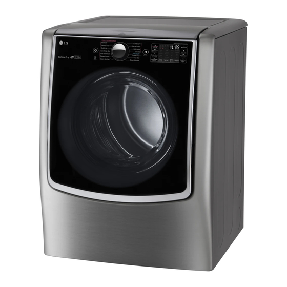
MODEL :
Any reproduction, duplication, distribution (including by way of email, facsimile or other electronic means),
publication, modification, copying or transmission of this Service Manual is STRICTLY PROHIBITED unless
you have obtained the prior written consent of the LG Electronics entity from which you received this Service
Manual. The material covered by this prohibition includes, without limitation, any text, graphics or logos in this
Service Manual.
Copyright ©
2016 - 2017
LG Electronics Inc. All rights reserved. Only training and service purposes.
Electric
DLEX9000*
DLEX9500*
Gas
DLGX9001*
DLGX9501*
CONFIDENTIAL
Advertisement
Table of Contents

Related Manuals for LG DLEX9500K


Summarization of Contents
Safety and Emergency Procedures
General Safety Warnings
Critical safety notices for appliance repair and operation.
Gas Leak Emergency Protocol
Steps to follow if a gas leak is detected, including evacuation and contacting authorities.
Electrostatic Discharge (ESD) Handling
Guidelines for safely handling sensitive electronic components to prevent damage.
Dryer Specifications
Technical Specifications
Details on power supply, size, capacity, and weight of the dryer.
Included and Optional Accessories
List and illustration of accessories that come with or can be added to the dryer.
Dryer Features and Controls
Control Panel Interface Types
Overview of the TT(D) Dial and TT(D) Full touch control interfaces.
Installation Instructions
Dryer Rack Installation
Step-by-step guide for installing the dryer rack inside the drum.
Electric Dryer Electrical Connections (4-Wire)
Details for connecting electric dryers using 4-wire receptacles or direct wiring.
Electric Dryer Electrical Connections (3-Wire)
Details for connecting electric dryers using 3-wire receptacles or direct wiring.
Gas Supply Connection
Instructions for connecting the gas supply to the dryer, including pipe types.
Water Inlet Hose Connection
Steps for connecting the water supply hose, including with/without washer configurations.
Dryer Cycle Process
Cycle Operation Parameters
Explains default settings, drying, cooling, and wrinkle care parameters for various cycles.
Component Testing Information
Thermal Cut-off and Thermostat Testing
Procedures for testing thermal cut-off, hi-limit, and outlet thermostats.
Switch and Lamp Testing
Procedures for testing door switch, idler switch, and LED lamp components.
Heater, Thermistor, and Gas Valve Testing
Procedures for testing heater, thermistor, motor, and gas valve components.
Igniter and Flame Detector Testing
Procedures for testing igniter and flame detector components.
Outlet Thermostat and Inlet Valve Testing
Procedures for testing outlet thermostats and the inlet valve.
Motor Diagram and Schematic
Motor Operation and Testing
Diagrams and resistance checks for motor stop and run modes.
Wiring Diagram
Electric Dryer Wiring Diagram
Detailed wiring schematic for electric dryer models.
Gas Dryer Wiring Diagram
Detailed wiring schematic for gas dryer models.
Steam Function
Steam Cycle Guide
Details on steam cycles, default times, temperature, and fabric types.
Steam Function Troubleshooting
Common Steam Dryer Problems and Solutions
Addresses common issues encountered with steam dryer functions and their resolutions.
Steam Function Error Codes
Display Fault Codes for Steam Dryers
Lists and explains error codes displayed during steam dryer operation or testing.
Flow Sensor Function
FlowSense™™ Operation
Explains the FlowSense™™ function for detecting duct clogging and triggering alarms.
Flow Sensor Installation Test
Duct Check Procedure
Procedure to test exhaust system condition using the FlowSense™™ installation test.
Flow Sensor Troubleshooting
Airflow Restriction and Error Code Solutions
Addresses troubleshooting for airflow restrictions and specific error codes.
Diagnostic Test Mode
Activating the Diagnostic Test
Steps to enter and operate the diagnostic test mode for troubleshooting.
Diagnostic Test Procedures
Test 1: 120V AC Electrical Supply Check
Procedure to verify the 120V AC electrical supply to the controller.
Test 1: Power Connection and Status Check
Checks tab relay connections to PCB for electric and gas models.
Incorrect Connection Results
Details results of incorrect tab relay and connector housing connections.
Test 2: Thermistor Resistance Measurement
Procedure to measure thermistor resistance with power off.
Test 3: Motor Function Testing
Procedure to test motor by measuring resistance and checking related components.
Test 4: Moisture Sensor Check
Procedure to test the moisture sensor by measuring resistance and voltage.
Test 5: Door Switch Functionality
Procedure to test the door switch by measuring resistance in different states.
Test 6: Electric Heater Switch Test
Procedure to test heater switches and thermostats in electric models.
Test 7: Gas Valve Operation Test
Procedure to test the gas valve by checking voltage, resistance, and igniter.
Test 8: DC Pump and Motor Assembly Test
Procedure to test the DC pump using diagnostic test mode and checking AD value.
Gas Type Conversion
Changing Gas Setting (Natural to Propane)
Instructions for converting the dryer's gas setting from natural to propane.
Gas Valve Operation
Gas Valve Flowchart
Illustrates the operational sequence of the gas valve, igniter, and flame detection.
Disassembly Instructions
Top Plate Removal
Step-by-step guide for safely removing the dryer's top plate.
Top Plate Component Removal
Detailed steps for removing dispenser cover, protective cover, and body frame.
Lid and Cover Guide Removal
Steps for disassembling the lid assembly and cover guides.
Cabinet Cover and Panel Frame Removal
Instructions for removing the dryer's cabinet cover and panel frame.
Drum Assembly and Drum Light Replacement
Steps for accessing, removing the drum assembly, and replacing the drum light.
Dryer Maintenance
Dryer Exhaust System Installation
Guide for installing or changing the dryer exhaust ductwork.
Air Duct and Filter Assembly Servicing
Steps for removing and servicing the air duct and filter assembly.
Blower Housing, Back Cover, and Roller Servicing
Disassembly instructions for blower housing, back cover, and rollers.
Inlet Water Hose Replacement
Procedure for replacing the dryer's inlet water hose.
Generator Area Hose Replacement
Steps for removing and replacing hoses connected to the generator.
Steam Harness and Generator Component Replacement
Instructions for replacing steam harness and generator components.
Steam Generator Cover and Bracket Servicing
Steps for removing and reassembling the steam generator cover and bracket.
Component Replacement
Main PCB and Display PCB Replacement
Guide for replacing the main control board (PCB) and display PCB.
Exploded Views
Plate Assembly Exploded View
Illustrated breakdown of the dryer's plate assembly components.
Cabinet and Door Assembly (Electric Dial)
Exploded view of the cabinet and door for electric dial models.
Cabinet and Door Assembly (Gas Dial)
Exploded view of the cabinet and door for gas dial models.
Cabinet and Door Assembly (Electric Full Touch)
Exploded view of the cabinet and door for electric full touch models.
Cabinet and Door Assembly (Gas Full Touch)
Exploded view of the cabinet and door for gas full touch models.
Drum and Motor Assembly (Electric Type)
Exploded view of the drum and motor assembly for electric models.
Drum and Motor Assembly (Gas Type)
Exploded view of the drum and motor assembly for gas models.
Need help?
Do you have a question about the DLEX9500K and is the answer not in the manual?
Questions and answers