Advertisement
Quick Links
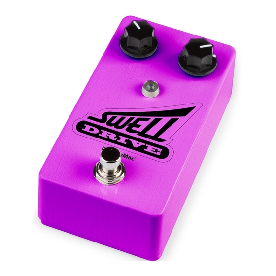
BASED ON THE
RARE AND ICONIC
BOSS SLOW GEAR,
an effect that gives the sound of a volume control being
rolled up after a note or chord is hit. A single obsolete
component prevents this pedal from being mass produced
but we have found a stash that enables us to offer these
kits. When they're gone, they're gone!
©2020 StewMac • All rights reserved • i-2355 Updated September 2020
SWELL DRIVE
PEDAL KIT
INSTRUCTION GUIDE
POWER
This pedal requires a standard 9V DC center-negative
power supply (not included) and consumes less than
100mA. There's no battery option.
TECHNICAL SUPPORT
If you have any questions before, during, or after this
project, please do not hesitate to reach out to our
Tech Support Team. They are available by email at
service@stewmac.com.
stewmac.com
22nJ
1uF
10uF
10uF
1uF
1uF
1uF
1uF
10uF
08 EDT
1uF
IN GND SW OUT
Advertisement

Related Manuals for StewMac SWELL DRIVE


Summary of Contents for StewMac SWELL DRIVE
- Page 1 When they’re gone, they’re gone! Tech Support Team. They are available by email at service@stewmac.com. ©2020 StewMac • All rights reserved • i-2355 Updated September 2020 stewmac.com...
- Page 2 PARTS LIST TOOLS AND SUPPLIES (REQUIRED) Guitar Tech Screwdriver and Wrench Set #3693 Fine-gauge Wire Stripper #1606 Soldering Iron #0502 Solder Wick #0504 Solder #0505 Wire Cutter #1607 Long-nose pliers #1610 TOOLS AND SUPPLIES (HELPFUL) Soldering Aids #0521 Multimeter #3607 PC Board Holder 3M Gold Fre-Cut #0500...
- Page 3 PARTS LIST Resistor values are indicated by color bands, read from left to right. The first color in the code is usually the one painted closer to a lead wire. See more about resistor color codes on page 5. 390 resistor (1) 47K resistor (1) #7349 #7369...
- Page 4 PARTS LIST (CONT) 08 EDT 10K trim pot (1) 24" of lead wire (1) #5960 #7570 5mm white LED (1) B25K linear taper attack pot (1) #7422 #7461 5mm LED mounting bezel (1) B100K linear taper sensitivity pot (1) #7432 #7453 TL071 low noise distortion op-amp (1) Adhesive foam tape square (4)
- Page 5 MORE HELPFUL The solder joints you’ll make on the printed circuit SOLDERING SOLDERING TIPS board are very small, and too much heat can damage AND TRICKS the board. The idea is to make joints quickly, without scorching the eyelets. • Keep your soldering tip clean by wiping it often Hold components in place for soldering by...
- Page 6 called nanofarads (nF), or trillionths of a farad, called UNDERSTANDING ELECTRONIC picofarads (pF). .001μF = 1nF = 1,000pF. COMPONENTS Resistors and capacitors may also be referred to with CAPACITORS shorthand notation on the printed circuit board The two main uses of capacitors are to store when there is a decimal in the value.
- Page 7 Audio taper is used because our ears don’t hear UNDERSTANDING ELECTRONIC changes in volume in a linear fashion as you might COMPONENTS expect. As the volume increases, a greater change in signal or sound pressure is required to perceive a POTENTIOMETERS smooth transition.
- Page 8 It’s time to install your parts! Before soldering the diodes and transistors to your printed circuit board, make sure you thread the leads through the correct side. The side of the printed circuit board INSTALL that has white values and outlines of the components is the correct 5 DIODES side.
- Page 9 1M resistor (1) #7367 BrownB lack BlackY ellowB rown 470K resistor (2) Resistors have a low profile, sitting closer to the board #7382 Yellow Purple BlackO range Brown than taller components, so installing these now will make installing other parts easier later on. 470K 100K resistor (1) #7365...
- Page 10 The remaining capacitors below are not polarized. However, best practice is to solder these caps in place all facing the same direction when possible. INSTALL 7 CAPACITORS 470nF capacitor (1) #7336 22nJ 22nF capacitor (2) 10µF capacitor (2) 10uF #7317 #7338 1nF capacitor (1) 102J...
- Page 11 Install the trim pot with the text facing the top of the board, as shown in the diagram. This is a very small potentiometer that fine-tunes the pedal’s effect on the signal, especially the attack. Use a screwdriver to set the trim pot to the midpoint of its range. INSTALL THE Near this midpoint is where we get the best results, but feel free to experiment with TRIM POT...
- Page 12 Orient the breakout board with the text facing You can use the pedal up, reading left to right. Slide the lugs of the enclosure as a mount for footswitch up through the bottom of the board. the footswitch while you INSTALL FOOTSWITCH solder the breakout board...
- Page 13 The last components to go onto TIME the printed circuit board are the ATTACK SENSITIVITY (B25K) (A100K) sensitivity and attack pots. They INSTALL 2 install on the back of the board. POTS AND Each pot has three connecting ATTACH lugs. Note the orientation of FOAM TAPE each pot.
- Page 14 Like some of the caps and diodes, the LED is polarized and has to be installed in a specific direction. The negative lead of the diode has a flat INSTALL edge and is shorter than the positive. INDICATOR LIGHT The LED mounting bezel consists of two main parts: A ring that the LED fits into, and a plastic plug that goes over the LED from the back side to keep it in place.
- Page 15 Insert the DC power jack into the center hole in the top of the enclosure making sure the longer of the two lugs is on the left. Use a 14mm wrench on the included nut to secure the jack into the enclosure. INSTALL THE DC Solder the inside left wire to the longer lug of the DC jack.
- Page 16 Insert the output jack into the right side hole in the top of the enclosure with the tip connection facing up, as shown in the diagram. Add the washer, and thread the nut onto the shaft enough so that the jack can rotate freely. You may need to rotate the INSTALL jack to provide easier access to setting the solder joints.
- Page 17 HERE’S HOW THE CONTROLS WORK POWER: Use a standard 9 volt DC power supply with a 2.1mm negative-center barrel (not included). We always recommend pedal-specific, transformer-isolated, wall-wart power supplies or supplies with separate isolated outputs. Pedals will make extra noise if there is ripple or unclean power. Switching-type power supplies, daisy chains, and non-pedal specific power supplies do not filter dirty power as well and let through unwanted noise.
Need help?
Do you have a question about the SWELL DRIVE and is the answer not in the manual?
Questions and answers