Advertisement
Quick Links
Advertisement

Related Manuals for StewMac FAN TREMOLO


Summary of Contents for StewMac FAN TREMOLO
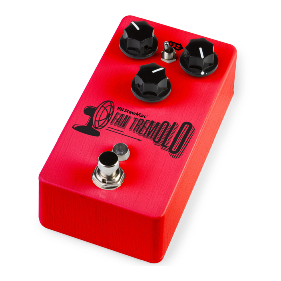
- Page 1 FAN TREMOLO 1J63 PEDAL KIT INSTRUCTION GUIDE IN GND SW OUT...
- Page 2 FROM PARTS LIST POWER TOOLS AND SUPPLIES (REQUIRED) Guitar Tech Screwdriver REQUIRED and Wrench Set VINTAGE #3696 This pedal requires a standard 9V DC center- negative power supply (not included) and WARBLE consumes less than 100mA. There’s no battery Soldering Iron option.
- Page 3 PARTS LIST TOOLS AND SUPPLIES (HELPFUL) Resistor values are indicated by colored bands, read from left to right. The first color in the code is usually the one painted closest to a lead wire. When a gold or silver band is present, it’s always one of the last colors in the code. 100 resistor (1) 22K resistor (1) #7379...
-
Page 4: Parts List (Cont)
PARTS LIST (CONT) PARTS LIST (CONT) 1µF capacitor (2) 100nF capacitor (1) 5mm LED mounting bezel (1) 1u F #7304 #7432 #7337 B10K linear taper pot (1) #7532 B100K linear taper pot (2) PF5102 transistor (1) #7453 220nF capacitor (1) #7518 10µF capacitor (1) 1 0 u F... - Page 5 MORE HELPFUL SOLDERING PARTS LIST (CONT) The solder joints you’ll make on the circuit boards are very SOLDERING TIPS small, and too much heat can damage the board. The idea is to make joints AND TRICKS quickly, without scorching the eyelets. •...
- Page 6 CAPACITORS UNDERSTANDING ELECTRONIC Band 1 Band 2 Band 3 Band 4 Band 4 Resistors and capacitors may also be referred to with The two main uses of capacitors are to store COMPONENTS 1st Digit 2nd Digit 3rd Digit Multiplier Tolerance shorthand notation on the printed circuit board BLACK electricity and to block the flow of DC current.
-
Page 7: Integrated Circuits
POTENTIOMETER Audio taper is used because our ears don’t hear UNDERSTANDING ELECTRONIC TL072CP A potentiometer, or pot, is a variable changes in volume in a linear fashion as you might COMPONENTS TL072CP low noise INTEGRATED CIRCUITS resistor. This means as the knob expect. - Page 8 45 mins between coats. 3. Cover the holes from the #7515 inside with masking tape. 1N5817 rectifier diode (1) 7. Now, add your Fan Tremolo 2N5089 transistor (1) #7522 #7514 sticker and any other desired 4. On a large piece of cardboard, 1N4148 rectifier diode (2)
- Page 9 Resistors have a low profile, sitting closer to the board Next, we’re going to add a bunch of resisitors to our PCB. Like in the previous step, you’ll than taller components, so installing these now will make find an outline of each resistor and its value printed in their proper location on the PCB. Match resistors to the values on the PCB and solder in place.
- Page 10 The three types of capacitors shown below are polarized and have to be installed in The remaining capacitors below are not polarized. 100nF capacitor (1) the correct orientation. Note the stripe running the length of each cap; this identifies However, best practice is to solder these caps in #7304 the negative (minus) lead.
- Page 11 One 3-way toggle switch is included with the kit. Slide the switch lugs through the back of the the three PCB holes at the top of the board and solder them. INSTALL 8 INSTALL 1 You can use the pedal enclosure as a mount for the toggle switch while you solder the SWITCH LEAD WIRES PCB board to it.
- Page 12 Orient the breakout board with the text facing up, Just like the toggle switch and the reading left to right, and slide the lugs of the footswitch PCB, you can use 1J63 up through the bottom of the board. the pedal enclosure INSTALL ATTACH 6 FOOTSWITCH...
- Page 13 The last components to go onto Solder the pots in place, making sure the foam back stays on the back of the pot. TIME RATE DEPTH the circuit board are the three This insulates the solder joints on the PCB from shorting to the housing of the pot. (B100K) (B10K) control pots.
- Page 14 Like some of the caps and diodes, The circuit board is held in place by the the LED is polarized and has to be control pots, but the LED leads need to installed in a specific direction. The pass through their eyelets in the PCB INSTALL 1 negative lead of the diode has a flat before the pots will pass through the...
- Page 15 Insert the DC jack into the top of the housing making sure the longer of the two lugs Insert the input jack into the left side of the housing with the tip connection facing is on the left. Using a 14mm wrench and 14mm nut, secure jack into housing. down, as shown in the diagram.
- Page 16 Insert the output jack into the right side of the housing with the tip connection facing up, as shown in the diagram. Add the washer and thread the nut on to the shaft enough so that the pot can rotate freely. You may need to rotate the jack to provide INSTALL COMPLETED easier access to setting the solder joints.
- Page 17 OUTPUT INPUT HERE’S HOW THE CONTROLS WORK 9V DC 1 3 2 POWER: Use a standard 9 volt DC power MODE: This 3-way toggle switch selects which supply with a 2.1mm negative-center barrel (not type of oscillation you would like. All the way left included).
- Page 18 IN GND SW OUT...
-
Page 19: Technical Support
Tech Support Team. They are available by email at service@stewmac.com. 21 N. Shafer St., Athens, OH 45701 stewmac.com ©2020 StewMac. All rights reserved. • #2351 Updated February 2020...
Need help?
Do you have a question about the FAN TREMOLO and is the answer not in the manual?
Questions and answers