Advertisement
Quick Links
THIS PEDAL IS A HOT-
RODDED VERSION OF
THE CLASSIC IBANEZ
TUBE SCREAMER.
We've made a few tweaks to make this game-changing
pedal even more versatile. Compared to most modern
overdrive pedals, the Screamer is relatively transparent and
won't totally change your tone. The idea of this circuit is
not to distort the signal on its own but to push the preamp
tubes of your amp into screaming distortion.
©2020 StewMac • All rights reserved • i-2350 Updated September 2020
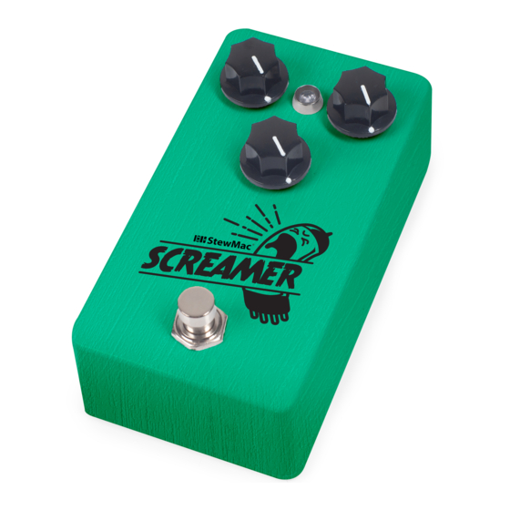
SCREAMER
PEDAL KIT
INSTRUCTION GUIDE
POWER
This pedal requires a standard 9V DC center-negative
power supply (not included) and consumes less than
100mA. There's no battery option.
TECHNICAL SUPPORT
If you have any questions at all, our Tech Support Team
is here to help. Email us at service@stewmac.com, and
we'll respond quickly!
stewmac.com
.22J63
IN GND SW OUT
Advertisement

Subscribe to Our Youtube Channel
Related Manuals for StewMac SCREAMER


Summary of Contents for StewMac SCREAMER
- Page 1 Email us at service@stewmac.com, and not to distort the signal on its own but to push the preamp we’ll respond quickly! tubes of your amp into screaming distortion. ©2020 StewMac • All rights reserved • i-2350 Updated September 2020 stewmac.com...
- Page 2 PARTS LIST TOOLS AND SUPPLIES (REQUIRED) Guitar Tech Screwdriver and Wrench Set #3693 Fine-gauge Wire Stripper #1606 Soldering Iron #0502 Solder Wick #0504 Solder #0505 Wire Cutter #1607 Long-nose pliers #1610 TOOLS AND SUPPLIES (HELPFUL) Soldering Aids #0521 Multimeter #3607 PC Board Holder 3M Gold Fre-Cut #0500...
-
Page 3: Parts List
PARTS LIST Resistor values are indicated by color bands, read from left to right. The first color in the code is usually the one painted closer to a lead wire. See more about resistor color codes on page 5. 100 resistor (1) 10K resistor (7) #7352 #7362... -
Page 4: Parts List (Cont)
PARTS LIST (CONT) B25K linear taper tone pot (1) 5mm LED mounting bezel (1) #7461 #7432 B100K linear taper volume pot (1) #7455 JRC4558D op-amp integrated circuit (1) #7446 A500K audio taper drive pot (1) #7458 Integrated circuit socket (1) #7484 Adhesive foam tape square (4) #7560... - Page 5 MORE HELPFUL The solder joints you’ll make on the printed circuit SOLDERING SOLDERING TIPS board are very small, and too much heat can damage AND TRICKS the board. The idea is to make joints quickly, without scorching the eyelets. • Keep your soldering tip clean by wiping it often Hold components in place for soldering by...
- Page 6 (op-amps), which multiply the input signal. each diode so that its stripe matches the direction shown on the printed circuit board. The integrated circuit in this pedal is a JRC4558D op- amp as used in the original TS-808 Tube Screamer.
- Page 7 UNDERSTANDING ELECTRONIC COMPONENTS TRANSISTORS Transistors are used to amplify electrical signals. They have a flat side and a round side. The location on the printed circuit board also has a flat side and a round side. Match the orientation of the component to this outline.
- Page 8 You’re creating a pedal from the ground up, so add your own custom paint job too! Painting your pedal and adding the stickers provided in this kit (or custom decals that you can create on your own) in advance is not only fun, but it’s much easier than PAINTING disassembling the pedal to paint it once you have put it together.
- Page 9 Next, we’re going to add a bunch of resistors to our printed circuit board. As in the previous step, you’ll find an outline of each resistor and its value printed in their proper location on the printed circuit board. Match resistors to the values on the printed circuit INSTALL 19 board and solder in place.
- Page 10 The three types of capacitors shown below are polarized and must be installed in the correct orientation. Note the stripe running the length of each cap; this identifies the negative (–) lead (the negative lead is also shorter). INSTALL 5 CAPACITORS On the printed circuit board, each capacitor has a square-shaped eyelet marked positive (+).
- Page 11 PT2399 heat, and it allows you to experiment with different op-amps. We’ve supplied a JRC4558D echo audio op-amp, as in the TS-808 Tube Screamer. You can explore different sounds by swapping processor (1) #7490 op-amps. For example, try the TL072CP Klon Centaur style op-amp (StewMac #7444).
- Page 12 Orient the breakout board with the text facing You can use the pedal up, reading left to right. Slide the lugs of the enclosure as a mount for footswitch up through the bottom of the board. the footswitch while you INSTALL FOOTSWITCH solder the breakout board...
- Page 13 The last components to go onto TIME DRIVE the printed circuit board are the VOLUME (A500K) (B100K) three control pots. They install INSTALL 3 on the back of the board. Each POTS AND pot has three connecting lugs. ATTACH Note the orientation of each FOAM TAPE pot.
- Page 14 Like some of the caps and diodes, the LED is polarized and has to be installed in a specific direction. The negative lead of the diode has a flat INSTALL edge and is shorter than the positive. INDICATOR LIGHT The LED mounting bezel consists of two main parts: A ring that the LED fits into, and a plastic plug that goes over the LED from the back side to keep it in place.
- Page 15 Insert the DC power jack into the center hole in the top of the enclosure making sure the longer of the two lugs is on the left. Use a 14mm wrench on the included nut to secure the jack into the enclosure. INSTALL THE DC Solder the inside left wire to the longer lug of the DC jack.
- Page 16 Insert the output jack into the right side hole in the top of the enclosure with the tip connection facing up, as shown in the diagram. Add the washer, and thread the nut onto the shaft enough so that the jack can rotate freely. You may need to rotate the INSTALL jack to provide easier access to setting the solder joints.
- Page 17 HERE’S HOW THE CONTROLS WORK VOLUME: This is a master volume control for the pedal. Turn it up and the signal gets stronger. Turn it down and the signal gets quieter. Increasing the volume can also increase the distortion in your amp by hitting the preamp tubes with a stronger signal, but it does not increase the distortion from the pedal.
Need help?
Do you have a question about the SCREAMER and is the answer not in the manual?
Questions and answers