Advertisement
Quick Links
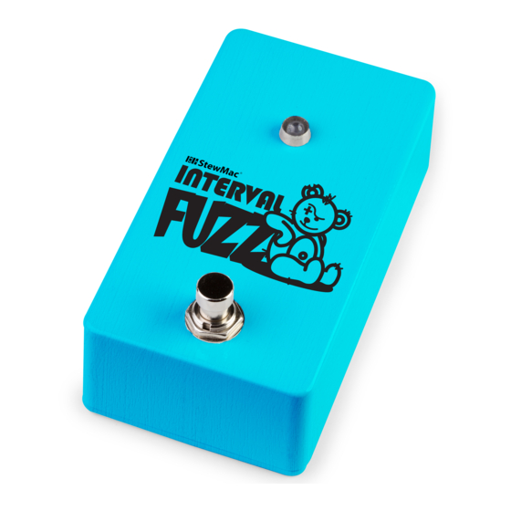
HIT THE SWITCH
AND GET YOUR
PURPLE HAZE ON!
This pedal doesn't need any knobs to send your signal
into over-the-top fuzz and octave up tones. Although this
no-knob fuzz doesn't have any controls on the pedal, it's
easy to coax different effects out of it. The pedal is very
responsive to different pickups. Humbuckers will produce a
more saturated fuzz than single-coil pickups will.
©2020 StewMac • All rights reserved • i-2354 Updated September 2020
INTERVAL FUZZ
PEDAL KIT
INSTRUCTION GUIDE
POWER
This pedal requires a standard 9V DC center-negative
power supply (not included) and consumes less than
100mA. There's no battery option.
TECHNICAL SUPPORT
If you have any questions at all, our Tech Support Team
is here to help. Email us at service@stewmac.com, and
we'll respond quickly!
stewmac.com
IN GND SW OUT
Advertisement

Related Manuals for StewMac INTERVAL FUZZ


Summary of Contents for StewMac INTERVAL FUZZ
- Page 1 The pedal is very is here to help. Email us at service@stewmac.com, and responsive to different pickups. Humbuckers will produce a we’ll respond quickly! more saturated fuzz than single-coil pickups will. ©2020 StewMac • All rights reserved • i-2354 Updated September 2020 stewmac.com...
- Page 2 PARTS LIST TOOLS AND SUPPLIES (REQUIRED) Guitar Tech Screwdriver and Wrench Set #3693 Soldering Iron #0502 Solder Wick #0504 Fine-gauge Wire Solder #0505 Stripper #1606 Wire Cutter #1607 TOOLS AND SUPPLIES (HELPFUL) Soldering Aids #0521 Multimeter #3607 PC Board Holder 3M Gold Fre-Cut #0500 Sandpaper (220-grit)
-
Page 3: Parts List
PARTS LIST Resistor values are indicated by colored bands, read from left to right. The first color in the code is usually the one painted closest to a lead wire. See more about resistor color codes on page 5. 4.7K resistor (1) 47K resistor (1) #7359 #7369... - Page 4 PARTS LIST (CONT) Printed circuit board (1) 24" of lead wire (1) #5960 IN GND SW OUT 5mm white LED (1) Breakout board (1) #7422 5mm LED mounting bezel (1) 3PDT latching footswitch (1) #7432 #1611 2.1mm DC power jack (1) #7468 1/4"...
- Page 5 MORE HELPFUL The solder joints you’ll make on the printed circuit SOLDERING SOLDERING TIPS board are very small, and too much heat can damage AND TRICKS the board. The idea is to make joints quickly, without scorching the eyelets. • Keep your soldering tip clean by wiping it often Hold components in place for soldering by...
- Page 6 called nanofarads (nF), or trillionths of a farad, called UNDERSTANDING ELECTRONIC picofarads (pF). .001μF = 1nF = 1,000pF. COMPONENTS Resistors and capacitors may also be referred to with CAPACITORS shorthand notation on the printed circuit board The two main uses of capacitors are to store when there is a decimal in the value.
- Page 7 UNDERSTANDING ELECTRONIC COMPONENTS LEDs LED stands for Light Emitting Diode, and functionally LEDs are very similar to regular diodes. LEDs are most often used as indicator lights in pedals. They are polarized just like diodes and electrolytic capacitors and must be installed in the correct orientation to work.
- Page 8 It’s time to install your parts! Before soldering the diodes to your printed circuit board, make sure you thread the leads through the correct side. The side of the printed circuit board that has white values and outlines of the components is the correct side. In some INSTALL 3 cases, components must insert into the printed circuit board in a specific direction due DIODES...
- Page 9 Resistors have a low profile, sitting closer to the board than taller components, so installing these now will make installing INSTALL other parts easier later on. 6 MORE RESISTORS 160K resistor (1) #7415 Brown Blue Black Orange Brown 68K resistor (2) #7380 Blue Gray Black Red Brown 560K resistor (1)
- Page 10 Transistors are directional and need to be installed in a specific orientation. Note that each one has a flat side. On the printed circuit board the location outline INSTALL 3 also has a flat side. Install each transistor to match the TRANSISTORS outline. ...
- Page 11 Orient the breakout board with the text facing up, You can use the pedal reading left to right. Slide the lugs of the enclosure as a mount for footswitch up through the bottom of the board. the footswitch while you INSTALL FOOTSWITCH solder the breakout board...
- Page 12 Like some of the caps and diodes, the LED is polarized and has to be installed in a specific direction. The negative lead of the diode has a flat INSTALL edge and is shorter than the positive. INDICATOR LIGHT The LED mounting bezel consists of two main parts: A ring that the LED fits into and a plastic plug that goes over the LED from the back side to keep it in place.
- Page 13 Insert the DC power jack into the center hole in the top of the enclosure making sure the longer of the two lugs is on the left. Use a 14mm wrench on the included nut to secure the jack into the enclosure. INSTALL THE DC Solder the inside left wire to the longer lug of the DC jack.
- Page 14 Insert the output jack into the right side hole in the top of the enclosure with the tip connection facing up, as shown in the diagram. Add the washer and thread the nut onto the shaft enough so that the jack can rotate freely. You may need to rotate the INSTALL jack to provide easier access to setting the solder joints.
- Page 15 Similarly, placing a boost or distortion pedal in front of the Interval Fuzz will yield some amazingly dense and sputtering fuzz tones. If you’re looking for a more subtle effect, try rolling the volume knob back on your guitar. Experiment with putting this pedal in different parts of your signal chain to find where it works best for you.
Need help?
Do you have a question about the INTERVAL FUZZ and is the answer not in the manual?
Questions and answers