Table of Contents
Advertisement
Quick Links
Quick Installation Guide
PICO-APL1-SEMI
This document will guide you through
the basic installation process for your
new PICO-APL1-SEMI.
PICO-APL3-SEMI
Parts
1
Item
1
PICO-APL1 board
2
Top Chassis
3
Bottom Chassis
4
Heatsink
5
Accessory kits
Power Button Cable x1
Screw.M3. Black x8pcs
Screw.M3 Nickel x4pcs
2
Description
3
Remark/PN
MB
M1APL30010
M1APL30020
TH0APL1010
1709040104
S1D3004031
S1D5106010
4
5
Advertisement
Table of Contents

Related Manuals for Asus AAEON PICO-APL1-SEMI


Summary of Contents for Asus AAEON PICO-APL1-SEMI
- Page 1 Quick Installation Guide PICO-APL1-SEMI This document will guide you through the basic installation process for your new PICO-APL1-SEMI. PICO-APL3-SEMI Item Description Remark/PN PICO-APL1 board Top Chassis M1APL30010 Bottom Chassis M1APL30020 Heatsink TH0APL1010 Accessory kits Power Button Cable x1 1709040104 Screw.M3. Black x8pcs S1D3004031 Screw.M3 Nickel x4pcs S1D5106010...
- Page 2 Install Guide Steps PICO-KBU4-SEMI Quick Installation Guide Step 1: On the heatsink, remove the two plastic coverings as shown. Step 2: Place the top chassis onto the heatsink. Note the orientation of the chassis with the heatsink. Secure with four black screws. Step 3: On the PICO-APL1 board, remove the nut and washer from the power input port.
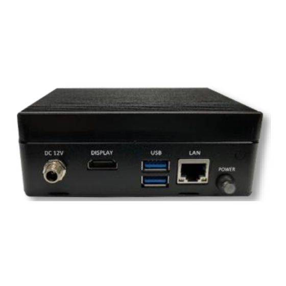
- Page 3 Step 7: Insert the PICO-APL1 board into the Step 8: Check that the I/O ports are properly chassis assembly with the processor side toward aligned. Secure board with four nickel screws. the heatsink. DO NOT place the CMOS battery between the board and heatsink. Step 9: Thread the power button cable through the hole for the power button.
- Page 4 Step 13: Replace the washer and nut for the power input port.
Need help?
Do you have a question about the AAEON PICO-APL1-SEMI and is the answer not in the manual?
Questions and answers