Table of Contents
Advertisement
Quick Links
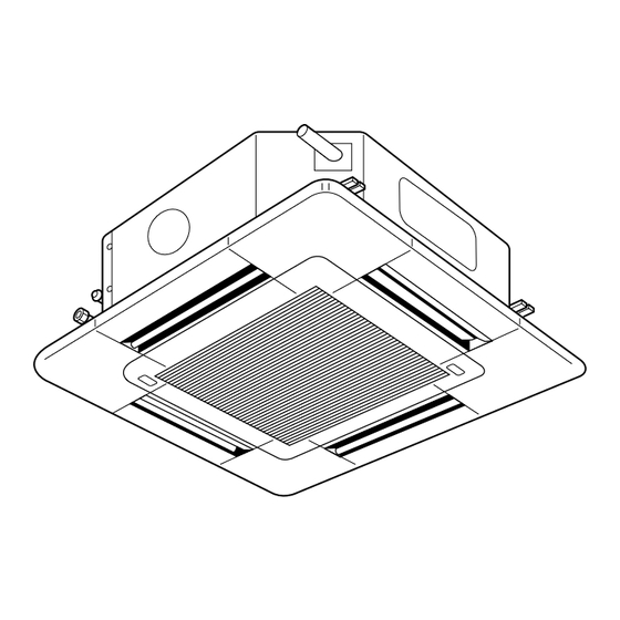
Air-Conditioners
PLH-3AK(H), 4, 5, 6AK(H)S
INSTALLATION MANUAL
E
For safe and correct use, please read this installation manual thoroughly before installing the air-conditioner unit.
INSTALLATIONSHANDBUCH
D
Zum sicheren und ordnungsgemäßen Gebrauch der Klimaanlage das Installationshandbuch gründlich durchlesen.
MANUEL D'INSTALLATION
F
Veuillez lire le manuel d'installation en entier avant d'installer ce climatiseur pour éviter tout accident et vous assurer d'une utilisation correcte.
INSTALLATIONSMANUAL
SD
Läs denna installationsmanual noga för säkert och korrekt bruk innan luftkonditioneringen installeras.
INSTALLATIEHANDLEIDING
NL
Voor een veilig en juist gebruik moet u deze installatiehandleiding grondig doorlezen voordat u de airconditioner installeert.
MANUALE DI INSTALLAZIONE
I
Per un uso sicuro e corretto, leggere attentamente questo manuale di installazione prima di installare il condizionatore d'aria.
MANUAL DE INSTALACIÓN
ES
Para un uso seguro y correcto, lea detalladamente este manual de instalación antes de montar la unidad de aire acondicionado.
MANUAL DE INSTALAÇÃO
PR
Para segurança e utilização correctas, leia atentamente este manual de instalação antes de instalar a unidade de ar condicionado.
INSTALLATIONSMANUAL
DK
Læs venligst denne installationsmanual grundigt, før De installerer airconditionanlægget, af hensyn til sikker og korrekt anvendelse.
E°XEIPI¢IO O¢H°IøN E°KATA™TA™H™
GR
°È· ·ÛÊ¿ÏÂÈ· Î·È ÛˆÛÙ‹ ¯Ú‹ÛË, ·Ú·Î·Ï›ÛÙ ‰È·‚¿ÛÂÙ ÚÔÛ¯ÙÈο ·˘Ùfi ÙÔ ÂÁ¯ÂÈÚ›‰ÈÔ ÂÁηٿÛÙ·Û˘ ÚÈÓ ·Ú¯›ÛÂÙ ÙËÓ ÂÁηٿÛÙ·ÛË Ù˘ ÌÔÓ¿‰·˜ ÎÏÈÌ·ÙÈÛÌÔ‡.
MONTAJ ELK‹TABI
TR
Emniyetli ve do¤ru biçimde nas›l kullan›laca¤›n› ö¤renmek için lütfen klima cihaz›n› monte etmeden önce bu elkitab›n› dikkatle okuyunuz.
РУКОВОДСТВО ПО УСТАНОВКЕ
RU
Для осторожного и правильного использования прибора необходимо тщательно ознакомиться с данным руководством по установке до выполнения установки кондиционера.
ON/OFF –
CENTRALLY CONTROLLED
1Hr.
ON OFF
FILTER
˚C
CHECK
CLOCK
CHECK MODE
TEST RUN
STAND BY
˚C
DEFROST
NOT AVAILABLE
FOR INSTALLER
FÜR INSTALLATEURE
POUR L'INSTALLATEUR
FÖR INSTALLATÖREN
VOOR DE INSTALLATEUR
PER L'INSTALLATORE
PARA EL INSTALADOR
PARA O INSTALADOR
TIL INSTALLATØREN
°π∞ ∞À∆√¡ ¶√À ∫∞¡∂π
∆∏¡ ∂°∫∞∆∞™∆∞™∏
MONTÖR ‹Ç‹N
ДЛЯ УСТАНОВИТЕЛЯ
Advertisement
Table of Contents

Related Manuals for Mitsubishi Electric mr.slim PLH-3AKS


Summary of Contents for Mitsubishi Electric mr.slim PLH-3AKS
- Page 1 Air-Conditioners PLH-3AK(H), 4, 5, 6AK(H)S FOR INSTALLER FÜR INSTALLATEURE POUR L’INSTALLATEUR FÖR INSTALLATÖREN VOOR DE INSTALLATEUR PER L’INSTALLATORE PARA EL INSTALADOR PARA O INSTALADOR TIL INSTALLATØREN °π∞ ∞À∆√¡ ¶√À ∫∞¡∂π ∆∏¡ ∂°∫∞∆∞™∆∞™∏ MONTÖR ‹Ç‹N ДЛЯ УСТАНОВИТЕЛЯ ON/OFF – CENTRALLY CONTROLLED 1Hr.
-
Page 2: Table Of Contents
Contents Contents Inhaltsverzeichnis Index Innehåll Inhoud Indice 1. Safety precautions ................... 4 2. Installation location ................12 3. Installing the indoor unit ................. 18 4. Installing the outdoor unit ............... 38 5. Installing the refrigerant piping ............... 40 6. Drainage piping work ................54 7. - Page 3 Contenido Índice Indholdsfortegnelse ¶ÂÚȯfiÌÂÓ· ‹çindekiler Содержание 1. Medidas de Seguridad ................5 1. Precauções de Segurança ..............5 2. Lugar en que se instalará ..............13 2. Localização da instalação ..............13 3. Instalación de la unidad interior ............. 19 3.
-
Page 4: Consignes De Sécurité
1. Safety precautions 1. Sicherheitsvorkehrungen 1. Consignes de sécurité 1. Säkerhetsåtgärder 1. Veiligheidsvoorschriften 1. Misure di sicurezza s Before installing the unit, make sure you read all the “Safety precau- tions”. s This equipment may not be applicable to EN60555-2:1987/EN61000-3- 2:1995+A1:1998+A2:1998 and/or EN60555-3:1987+A1:1991/EN61000-3- 3:1995. -
Page 5: Medidas De Seguridad
1. Medidas de Seguridad 1. Precauções de Segurança 1. Sikkerhedsforanstaltninger 1. ¶ÚÔÊ˘Ï·ÎÙÈο ª¤ÙÚ· ∞ÛÊ·Ï›·˜ 1. Güvenlik Önlemleri 1. Меры предосторожности s Antes de instalar la unidad, asegúrese de haber leído el capítulo de s s s s s Antes de instalar a unidade, leia atentamente as “Precauções de segu- “Medidas de seguridad”. - Page 6 1. Safety precautions 1. Sicherheitsvorkehrungen 1. Consignes de sécurité 1. Säkerhetsåtgärder 1. Veiligheidsvoorschriften 1. Misure di sicurezza : Indicates an action that must be avoided. : Indicates that important instructions must be followed. : Indicates a part which must be grounded. : Indicates that caution should be taken with rotating parts.
- Page 7 1. Medidas de seguridad 1. Precauções de segurança 1. Sikkerhedsforanstaltninger 1. ¶ÚÔÊ˘Ï·ÎÙÈο ª¤ÙÚ· ∞ÛÊ·Ï›·˜ 1. Güvenlik Önlemleri 1. Меры предосторожности : Indica una acción que debe evitarse. : Indica uma acção a evitar. : Indica que deben seguirse unas instrucciones importantes. : Indica a existência de instruções importantes a seguir.
- Page 8 • The unit should not be installed by the user. Ask the dealer or an authorized technician to install the unit. • Use only accessories authorized by Mitsubishi Electric and ask the dealer or an authorized technician to install them.
- Page 9 • Utilice sólo accesorios autorizados por Mitsubishi Electric y pida a su distri- • Utilize só acessórios autorizados pela Mitsubishi Electric e peça ao seu dis- buidor o a una empresa autorizada que se los instale.
- Page 10 1. Safety precautions 1. Sicherheitsvorkehrungen 1. Consignes de sécurité 1. Säkerhetsåtgärder 1. Veiligheidsvoorschriften 1. Misure di sicurezza Caution: • When the room humidity exceeds 80% or when the drain pipe is clogged, water may drip from the indoor unit. Do not install the indoor unit where such dripping could cause damage.
- Page 11 1. Medidas de seguridad 1. Precauções de segurança 1. Sikkerhedsforanstaltninger 1. ¶ÚÔÊ˘Ï·ÎÙÈο ª¤ÙÚ· ∞ÛÊ·Ï›·˜ 1. Güvenlik Önlemleri 1. Меры предосторожности Cuidado: Cuidado: • Cuando la humedad de la habitación supere el 80%, o cuando el tubo de • Se a humidade da peça exceder 80% ou o tubo de drenagem estiver entupido, drenaje esté...
-
Page 12: Emplacement Pour L'installation
2. Installation location 2. Aufstellort 2. Emplacement pour l’installation 2. Placering 2. Plaats 2. Luogo in cui installare Indoor unit 2.1. Outline dimensions (Indoor unit) (mm) Models PLH-3 PLH-4, 5, 6 Warning: Mount the indoor unit on a ceiling strong enough to withstand the weight of the unit. -
Page 13: Lugar En Que Se Instalará
2. Lugar en que se instalará 2. Localização da instalação 2. Montagested 2. ÃÒÚÔ˜ ÂÁηٿÛÙ·Û˘ 2. Montaj yeri 2. Место установки 2.1. Dimensiones exteriores (Unidad interior) 2.1. Dimensões globais (Unidade interior) (mm) (mm) Modelos Modelos PLH-3 PLH-3 PLH-4, 5, 6 PLH-4, 5, 6 Atención: Aviso:... - Page 14 2. Installation location 2. Aufstellort 2. Emplacement pour l’installation 2. Placering 2. Plaats 2. Luogo in cui installare 2.3. Refrigerant pipe s Check that the difference between the heights of the indoor and outdoor units, the length of refrigerant pipe, and the number of bends in the pipe are within the limits shown below.
- Page 15 2. Lugar en que se instalará 2. Localização da instalação 2. Montagested 2. ÃÒÚÔ˜ ÂÁηٿÛÙ·Û˘ 2. Montaj yeri 2. Место установки 2.3. Tubería de refrigerante 2.3. Tubo de refrigerante s Compruebe que la diferencia de altura entre las unidades interior y exte- s Verifique se a diferença entre as alturas das unidades interior e exterior, o rior, la longitud del tubo de refrigerante y la cantidad de codos en la tubería comprimento da tubagem de refrigeração e o número de curvas na tubagem...
- Page 16 2. Installation location 2. Aufstellort 2. Emplacement pour l’installation 2. Placering 2. Plaats 2. Luogo in cui installare 2.4. Ventilation and service space When installing a single outdoor unit A Min. 100 (150) mm When installing many outdoor units A Min. 100 (150) mm B Min.
- Page 17 2. Lugar en que se instalará 2. Localização da instalação 2. Montagested 2. ÃÒÚÔ˜ ÂÁηٿÛÙ·Û˘ 2. Montaj yeri 2. Место установки 2.4. Ventilación y espacio de servicio 2.4. Ventilação e espaço de manutenção Al instalar una unidad exterior simple Quando instalar uma só unidade exterior A Min.
-
Page 18: Installation De L'appareil Intérieur
3. Installing the indoor unit 3. Anbringung der Innenanlage 3. Installation de l’appareil intérieur 3. Installering av inomhusenheten 3. Het binnenapparaat installeren 3. Installazione della sezione interna 3.1. Check the indoor unit accessories The indoor unit should be supplied with the following accessories. Accessory name Q’ty Installation template... -
Page 19: Instalación De La Unidad Interior
3. Instalación de la unidad interior 3. Instalação da unidade interior 3. Montering af den indendørs enhed 3. ∂ÁηٿÛÙ·ÛË Ù˘ ÂÛˆÙÂÚÈ΋˜ ÌÔÓ¿‰·˜ 3. ‹ç ünitenin montaj› 3. Установка внутреннего прибора 3.1. Comprobación de los accesorios de la unidad interior 3.1. Verificação dos acessórios da unidade interior La unidad interior debe ir acompañada de los siguientes accesorios. - Page 20 3. Installing the indoor unit 3. Anbringung der Innenanlage 3. Installation de l’appareil intérieur 3. Installering av inomhusenheten 3. Het binnenapparaat installeren 3. Installazione della sezione interna 3.2. Ceiling openings and suspension bolt installation locations 860–910 20–45 20–45 • Using the installation template (top of the package) and the gauge (supplied as an accessory with the grille), make an opening in the ceiling so that the main unit can be installed as shown in the diagram.
- Page 21 3. Instalación de la unidad interior 3. Instalação da unidade interior 3. Montering af den indendørs enhed 3. ∂ÁηٿÛÙ·ÛË Ù˘ ÂÛˆÙÂÚÈ΋˜ ÌÔÓ¿‰·˜ 3. ‹ç ünitenin montaj› 3. Установка внутреннего прибора 3.2. Apertura del techo y ubicación de los tornillos de 3.2.
- Page 22 3. Installing the indoor unit 3. Anbringung der Innenanlage 3. Installation de l’appareil intérieur 3. Installering av inomhusenheten 3. Het binnenapparaat installeren 3. Installazione della sezione interna • Use M10 (3/8") suspension bolts. * Suspension bolts are to be procured at the field. 860–910 20–45 20–45...
- Page 23 3. Instalación de la unidad interior 3. Instalação da unidade interior 3. Montering af den indendørs enhed 3. ∂ÁηٿÛÙ·ÛË Ù˘ ÂÛˆÙÂÚÈ΋˜ ÌÔÓ¿‰·˜ 3. ‹ç ünitenin montaj› 3. Установка внутреннего прибора • Utilice tornillos de suspensión M10 (3/8"). • Utilize parafusos de suspensão M10 (3/8"). * Los tornillos de suspensión no están incluidos en el envío.
- Page 24 3. Installing the indoor unit 3. Anbringung der Innenanlage 3. Installation de l’appareil intérieur 3. Installering av inomhusenheten 3. Het binnenapparaat installeren 3. Installazione della sezione interna 3.3. Branch duct hole and fresh air intake hole At the time of installation, use the duct holes (cut out) located at the positions shown in following diagram, as and when required.
- Page 25 3. Instalación de la unidad interior 3. Instalação da unidade interior 3. Montering af den indendørs enhed 3. ∂ÁηٿÛÙ·ÛË Ù˘ ÂÛˆÙÂÚÈ΋˜ ÌÔÓ¿‰·˜ 3. ‹ç ünitenin montaj› 3. Установка внутреннего прибора 3.3. Orificio para conducciones y orificio para toma de 3.3. Orifício do conduto de derivação e orifício de ad- aire fresco missão de ar fresco Durante la instalación, utilice los orificios para conducciones (de corte) situados en...
- Page 26 3. Installing the indoor unit 3. Anbringung der Innenanlage 3. Installation de l’appareil intérieur 3. Installering av inomhusenheten 3. Het binnenapparaat installeren 3. Installazione della sezione interna A Branch duct hole B Indoor unit C Fresh air intake hole D Drain pipe E Refrigerant pipe F Branch duct hole diagram (view from either side) G Cut out hole...
- Page 27 3. Instalación de la unidad interior 3. Instalação da unidade interior 3. Montering af den indendørs enhed 3. ∂ÁηٿÛÙ·ÛË Ù˘ ÂÛˆÙÂÚÈ΋˜ ÌÔÓ¿‰·˜ 3. ‹ç ünitenin montaj› 3. Установка внутреннего прибора A Orificio para ramal de conducción A Orifício do conduto de derivação B Unidad interior B Unidade interior C Orificio para toma de aire fresco...
- Page 28 3. Installing the indoor unit 3. Anbringung der Innenanlage 3. Installation de l’appareil intérieur 3. Installering av inomhusenheten 3. Het binnenapparaat installeren 3. Installazione della sezione interna 3.4. Suspension structure (Give site of suspension strong structure) • The ceiling work differs according to the construction of the building. Buidling con- structors and interior decorators should be consulted for details.
- Page 29 3. Instalación de la unidad interior 3. Instalação da unidade interior 3. Montering af den indendørs enhed 3. ∂ÁηٿÛÙ·ÛË Ù˘ ÂÛˆÙÂÚÈ΋˜ ÌÔÓ¿‰·˜ 3. ‹ç ünitenin montaj› 3. Установка внутреннего прибора 3.4. Estructura de suspensión (Refuerzo de la estruc- 3.4. Estrutura de suspensão (Dar ao lugar de suspen- tura de suspensión) são uma estrutura forte) •...
- Page 30 3. Installing the indoor unit 3. Anbringung der Innenanlage 3. Installation de l’appareil intérieur 3. Installering av inomhusenheten 3. Het binnenapparaat installeren 3. Installazione della sezione interna 1 Wooden structures • Use tie beams (single storied houses) or second floor beams (two story houses) (mm) as reinforcing members.
- Page 31 3. Instalación de la unidad interior 3. Instalação da unidade interior 3. Montering af den indendørs enhed 3. ∂ÁηٿÛÙ·ÛË Ù˘ ÂÛˆÙÂÚÈ΋˜ ÌÔÓ¿‰·˜ 3. ‹ç ünitenin montaj› 3. Установка внутреннего прибора 1 Estructuras de madera 1 Estruturas de madeira • Use vigas-tirante (para casas de un solo piso) o vigas de doble piso (para casas •...
- Page 32 3. Installing the indoor unit 3. Anbringung der Innenanlage 3. Installation de l’appareil intérieur 3. Installering av inomhusenheten 3. Het binnenapparaat installeren 3. Installazione della sezione interna 3.5. Unit suspension procedures Suspend the main unit as shown in the diagram. Figures given in parentheses represent the dimensions in case of installing optional multi function casement.
- Page 33 3. Instalación de la unidad interior 3. Instalação da unidade interior 3. Montering af den indendørs enhed 3. ∂ÁηٿÛÙ·ÛË Ù˘ ÂÛˆÙÂÚÈ΋˜ ÌÔÓ¿‰·˜ 3. ‹ç ünitenin montaj› 3. Установка внутреннего прибора 3.5. Procedimientos de suspensión de la unidad 3.5. Processos de suspensão da unidade Suspenda la unidad principal como muestra el diagrama.
- Page 34 3. Installing the indoor unit 3. Anbringung der Innenanlage 3. Installation de l’appareil intérieur 3. Installering av inomhusenheten 3. Het binnenapparaat installeren 3. Installazione della sezione interna 3. When the main unit can not be aligned against the mounting hole on the ceiling, it is adjustable owing to a slot provided on the mounting plate.
- Page 35 3. Instalación de la unidad interior 3. Instalação da unidade interior 3. Montering af den indendørs enhed 3. ∂ÁηٿÛÙ·ÛË Ù˘ ÂÛˆÙÂÚÈ΋˜ ÌÔÓ¿‰·˜ 3. ‹ç ünitenin montaj› 3. Установка внутреннего прибора 3. Cuando la unidad principal no pueda ser alineada contra los orificios de montaje 3.
- Page 36 3. Installing the indoor unit 3. Anbringung der Innenanlage 3. Installation de l’appareil intérieur 3. Installering av inomhusenheten 3. Het binnenapparaat installeren 3. Installazione della sezione interna 3.6. Confirming the position of main unit and tighten- ing the suspension bolts •...
- Page 37 3. Instalación de la unidad interior 3. Instalação da unidade interior 3. Montering af den indendørs enhed 3. ∂ÁηٿÛÙ·ÛË Ù˘ ÂÛˆÙÂÚÈ΋˜ ÌÔÓ¿‰·˜ 3. ‹ç ünitenin montaj› 3. Установка внутреннего прибора 3.6. Confirmación de la posición de la unidad principal 3.6. Confirmação da posição da unidade principal e y apriete de los tornillos de sujeción aperto dos parafusos de suspensão •...
-
Page 38: Installation De L'appareil Extérieur
4. Installing the outdoor unit 4. Einbau der Außenanlage 4. Installation de l’appareil extérieur 4. Installation av utomhusenhet 4. Het buitenapparaat installeren 4. Installazione della sezione esterna • Be sure to install the unit in a sturdy, level surface to prevent rattling noises during operation. -
Page 39: Instalación De La Unidad Exterior
4. Instalación de la unidad exterior 4. Instalação da unidade exterior 4. Montering af den udendørs enhed 4. ∂ÁηٿÛÙ·ÛË Ù˘ Â͈ÙÂÚÈ΋˜ ÌÔÓ¿‰·˜ 4. D›fl ünitenin monte edilmesi 4. Установка наружного прибора • Cerciórese de instalar la unidad en una superficie robusta y nivelada para evitar •... -
Page 40: Installation De La Tuyauterie Du Réfrigérant
5. Installing the refrigerant piping 5. Installation der Kältemittelrohrleitung 5. Installation de la tuyauterie du réfrigérant 5. Installera kylmedelsrör 5. Installeren van de koelstofleidingen 5. Installazione della tubazione del refrigerante 5.1. Indoor unit • When commercially available copper pipes are used, wrap liquid and gas pipes with commercially available insulation materials (heat-resistant to 100 °C or more, thickness of 12 mm or more). -
Page 41: Instalación De Los Tubos Del Refrigerante
5. Instalación de los tubos del refrigerante 5. Instalação da tubagem do refrigerante 5. Montering af kølemiddelrør 5. ∂ÁηٿÛÙ·ÛË Ù˘ ۈϋӈÛ˘ „˘ÎÙÈÎÔ‡ ˘ÁÚÔ‡ 5. So¤utucu borular›n›n monte edilmesi 5. Прокладка труб хладагента 5.1. Unidad interior 5.1. Unidade interior • Si se utilizan tubos de cobre convencionales, envuelva los tubos de gas y líquido •... - Page 42 5. Installing the refrigerant piping 5. Installation der Kältemittelrohrleitung 5. Installation de la tuyauterie du réfrigérant 5. Installera kylmedelsrör 5. Installeren van de koelstofleidingen 5. Installazione della tubazione del refrigerante 5.2. Refrigerant and drainage piping locations The figure marked with * in the drawing represent the dimensions of the main unit excluding those of the optional multi function casement.
- Page 43 5. Instalación de los tubos del refrigerante 5. Instalação da tubagem do refrigerante 5. Montering af kølemiddelrør 5. ∂ÁηٿÛÙ·ÛË Ù˘ ۈϋӈÛ˘ „˘ÎÙÈÎÔ‡ ˘ÁÚÔ‡ 5. So¤utucu borular›n›n monte edilmesi 5. Прокладка труб хладагента 5.2. Ubicación de los tubos de refrigerante y drenaje 5.2.
- Page 44 5. Installing the refrigerant piping 5. Installation der Kältemittelrohrleitung 5. Installation de la tuyauterie du réfrigérant 5. Installera kylmedelsrör 5. Installeren van de koelstofleidingen 5. Installazione della tubazione del refrigerante 5.3. Refrigerant piping 1) Indoor unit 1.1. When using commercially available copper pipes: •...
- Page 45 5. Instalación de los tubos del refrigerante 5. Instalação da tubagem do refrigerante 5. Montering af kølemiddelrør 5. ∂ÁηٿÛÙ·ÛË Ù˘ ۈϋӈÛ˘ „˘ÎÙÈÎÔ‡ ˘ÁÚÔ‡ 5. So¤utucu borular›n›n monte edilmesi 5. Прокладка труб хладагента 5.3. Tubos de refrigerante 5.3. Tubagem de refrigerante 1) Unidad interior 1) Unidade interior 1.1.
- Page 46 5. Installing the refrigerant piping 5. Installation der Kältemittelrohrleitung 5. Installation de la tuyauterie du réfrigérant 5. Installera kylmedelsrör 5. Installeren van de koelstofleidingen 5. Installazione della tubazione del refrigerante A Refrigerant pipe and insulating material B Pipe cover (large) C Pipe cover (small) D Refrigerant pipe (gas) E Refrigerant pipe (liquid)
- Page 47 5. Instalación de los tubos del refrigerante 5. Instalação da tubagem do refrigerante 5. Montering af kølemiddelrør 5. ∂ÁηٿÛÙ·ÛË Ù˘ ۈϋӈÛ˘ „˘ÎÙÈÎÔ‡ ˘ÁÚÔ‡ 5. So¤utucu borular›n›n monte edilmesi 5. Прокладка труб хладагента A Tubo de refrigerante y material aislante A Tubo de refrigerante e material de isolamento B Tampa do tubo (grande) B Tapa del tubo (grande) C Tampa do tubo (pequeno)
- Page 48 5. Installing the refrigerant piping 5. Installation der Kältemittelrohrleitung 5. Installation de la tuyauterie du réfrigérant 5. Installera kylmedelsrör 5. Installeren van de koelstofleidingen 5. Installazione della tubazione del refrigerante 2) Outdoor unit 1 Pipe take-in direction The pipe can be passed in any of the four directions: front, rear, right and lower side. 2 Remove the service panel (three screws) and the piping cover (one screw).
- Page 49 5. Instalación de los tubos del refrigerante 5. Instalação da tubagem do refrigerante 5. Montering af kølemiddelrør 5. ∂ÁηٿÛÙ·ÛË Ù˘ ۈϋӈÛ˘ „˘ÎÙÈÎÔ‡ ˘ÁÚÔ‡ 5. So¤utucu borular›n›n monte edilmesi 5. Прокладка труб хладагента 2) Unidad exterior 2) Unidade exterior 1 Dirección de los tubos 1 Direcção sinuosa do tubo El tubo puede pasar por cualquiera de las cuatro direcciones: frontal, trasera, dere- O tubo pode ser dirigido em qualquer das quatro direcções: para a frente, para trás,...
- Page 50 5. Installing the refrigerant piping 5. Installation der Kältemittelrohrleitung 5. Installation de la tuyauterie du réfrigérant 5. Installera kylmedelsrör 5. Installeren van de koelstofleidingen 5. Installazione della tubazione del refrigerante 3) Stop valve 1 Perform refrigerant piping connections for the indoor/outdoor unit when the out- door unit’s stop valve is completely closed.
- Page 51 5. Instalación de los tubos del refrigerante 5. Instalação da tubagem do refrigerante 5. Montering af kølemiddelrør 5. ∂ÁηٿÛÙ·ÛË Ù˘ ۈϋӈÛ˘ „˘ÎÙÈÎÔ‡ ˘ÁÚÔ‡ 5. So¤utucu borular›n›n monte edilmesi 5. Прокладка труб хладагента 3) Válvula de tope 3) Válvula de paragem 1 Realice las conexiones de los tubos de refrigerante de la unidad interior/exterior 1 Execute as ligações da tubagem de refrigerante para a unidade interior/exterior con la válvula de parada de la unidad exterior completamente cerrada.
- Page 52 5. Installing the refrigerant piping 5. Installation der Kältemittelrohrleitung 5. Installation de la tuyauterie du réfrigérant 5. Installera kylmedelsrör 5. Installeren van de koelstofleidingen 5. Installazione della tubazione del refrigerante 5.4. Addition of refrigerant 1 Refrigerant amount This product needs no additional charging of refrigerant for a pipe length of 30 m or less.
- Page 53 5. Instalación de los tubos del refrigerante 5. Instalação da tubagem do refrigerante 5. Montering af kølemiddelrør 5. ∂ÁηٿÛÙ·ÛË Ù˘ ۈϋӈÛ˘ „˘ÎÙÈÎÔ‡ ˘ÁÚÔ‡ 5. So¤utucu borular›n›n monte edilmesi 5. Прокладка труб хладагента 5.4. Añadido de refrigerante 5.4. Adição de refrigerante 1 Cantidad de refrigerante 1 Quantidade de refrigerante Este producto no necesita una carga adicional de refrigerante si la tubería es de 30 m o...
-
Page 54: Mise En Place Du Tuyau D'écoulement
6. Drainage piping work 6. Verrohrung der Dränage 6. Mise en place du tuyau d’écoulement 6. Dräneringsrör 6. Installatie van Draineerbuizen 6. Installazione della tubazione di drenaggio Max. 20m 6.1. Drainage piping work • Use VP25 (O. D. ø32 PVC TUBE) for drain piping and provide 1/100 or more down- 1.5–2m ward slope. -
Page 55: Tubería De Drenaje
6. Tubería de drenaje 6. Trabalho de tubagem de drenagem 6. Føring af drænrør 6. ∂ÚÁ·Û›Â˜ ™ˆÏËÓÒÛÂˆÓ ∞Ô¯¤Ù¢Û˘ 6. Drenaj Tesisat› ‹flleri 6. Дренажные трубы 6.1. Tubería de drenaje 6.1. Trabalho de tubagem de drenagem • Utilice VP25 (tubo de PVC de ø32) para el tubo de drenaje y prevea una pendiente •... - Page 56 6. Drainage piping work 6. Verrohrung der Dränage 6. Mise en place du tuyau d’écoulement 6. Dräneringsrör 6. Installatie van Draineerbuizen 6. Installazione della tubazione di drenaggio 1. Connect the drain socket (supplied with the unit) to the drain port. (Affix the tube using PVC adhesive then secure it with a band.) 2.
- Page 57 6. Tubería de drenaje 6. Trabalho de tubagem de drenagem 6. Føring af drænrør 6. ∂ÚÁ·Û›Â˜ ™ˆÏËÓÒÛÂˆÓ ∞Ô¯¤Ù¢Û˘ 6. Drenaj Tesisat› ‹flleri 6. Дренажные трубы 1. Conecte el tubo de desagüe (suministrado con la unidad) al orificio de desagüe. 1. Ligue o bocal de drenagem (fornecido com a unidade) à porta de drenagem. (Sujete el tubo con cinta aislante y asegure la conexión con una abrazadera.) (Fixe o tubo com adesivo PVC e depois ate-o com uma banda.) 2.
-
Page 58: Installations Électriques
7. Electrical work 7. Elektroarbeiten 7. Installations électriques 7. Elektriska arbeten 7. Elektrische aansluitingen 7. Collegamenti elettrici 7.1. Precautions s Supply power from independently branched circuit. s Wiring should conform to applicable standards. Power supply Power supply s Never connect the power supply directly to the control wiring terminals, as this will cause a unit failure. -
Page 59: Trabajo Eléctrico
7. Trabajo eléctrico 7. Trabalho de electricidade 7. Elektrisk arbejde 7. ∏ÏÂÎÙÚÈΤ˜ ÂÚÁ·Û›Â˜ 7. Elektrik iflleri 7. Электрические работы 7.1. Precauciones 7.1. Precauções s La alimentación eléctrica debe ser una línea dedicada. s Fonte de alimentação do circuito ligado independentemente. s El cableado debe cumplir los estándares aplicables. - Page 60 7. Electrical work 7. Elektroarbeiten 7. Installations électriques 7. Elektriska arbeten 7. Elektrische aansluitingen 7. Collegamenti elettrici 1, 2 7.2. Indoor unit 1. Remove the two electrical wiring service panels. 2. Wire the power cable and control cable separately through the respective wiring entries given in the diagram.
- Page 61 7. Trabajo eléctrico 7. Trabalho de electricidade 7. Elektrisk arbejde 7. ∏ÏÂÎÙÚÈΤ˜ ÂÚÁ·Û›Â˜ 7. Elektrik iflleri 7. Электрические работы 7.2. Unidad interior 7.2. Unidade exterior 1. Saque dos paneles de servicio de cableado. 1. Retire os dois painéis de serviço da cablagem eléctrica. 2.
- Page 62 7. Electrical work 7. Elektroarbeiten 7. Installations électriques 7. Elektriska arbeten 7. Elektrische aansluitingen 7. Collegamenti elettrici 7.3. Remote controller 1) Installing procedures (1) Select an installing position for the remote controller. s Procure the following parts locally: Two piece switch box Thin copper conduit tube Lock nuts and bushings A Remote controller profile...
- Page 63 7. Trabajo eléctrico 7. Trabalho de electricidade 7. Elektrisk arbejde 7. ∏ÏÂÎÙÚÈΤ˜ ÂÚÁ·Û›Â˜ 7. Elektrik iflleri 7. Электрические работы 7.3. Control remoto 7.3. Controlo remoto 1) Procedimientos de instalación 1) Instruções de instalação (1) Seleccione una posición adecuada para el control remoto. (1) Seleccione uma posição de instalação do controlo remoto.
- Page 64 7. Electrical work 7. Elektroarbeiten 7. Installations électriques 7. Elektriska arbeten 7. Elektrische aansluitingen 7. Collegamenti elettrici (2) Seal the service entrance for the remote controller cord with putty to prevent possible invasion of dew drops, water, cockroaches or worms. A For installation in the switch box: B For direct installation on the wall select one of the following: •...
- Page 65 7. Trabajo eléctrico 7. Trabalho de electricidade 7. Elektrisk arbejde 7. ∏ÏÂÎÙÚÈΤ˜ ÂÚÁ·Û›Â˜ 7. Elektrik iflleri 7. Электрические работы (2) Selle la entrada del cable del control remoto con masilla para evitar que puedan (2) Vede a entrada de serviço do fio do controlo remoto com betume para evitar a entrar gotas de rocío, agua, cucarachas o gusanos.
- Page 66 7. Electrical work 7. Elektroarbeiten 7. Installations électriques 7. Elektriska arbeten 7. Elektrische aansluitingen 7. Collegamenti elettrici 2) Connecting procedures 1 Connect the remote controller cord to the terminal block of the lower case. A To TB5 on the indoor unit B TB6 (No polarity) 2 Set the Main OFF/Sub (subordinate) ON switch (see diagram) when using two remote controller’s for the same group.
- Page 67 7. Trabajo eléctrico 7. Trabalho de electricidade 7. Elektrisk arbejde 7. ∏ÏÂÎÙÚÈΤ˜ ÂÚÁ·Û›Â˜ 7. Elektrik iflleri 7. Электрические работы 2) Procedimientos de conexión 2) Instruções de instalação 1 Conecte el cable del control remoto en el bloque de terminales de la caja inferior. 1 Ligue o fio de controlo remoto ao bloco terminal da caixa inferior.
- Page 68 7. Electrical work 7. Elektroarbeiten 7. Installations électriques 7. Elektriska arbeten 7. Elektrische aansluitingen 7. Collegamenti elettrici 3 Connect the lower case connector to the upper case connector CN0. 4 Wiring port for direct installation of remote controller on the wall (In case of open wiring).
- Page 69 7. Trabajo eléctrico 7. Trabalho de electricidade 7. Elektrisk arbejde 7. ∏ÏÂÎÙÚÈΤ˜ ÂÚÁ·Û›Â˜ 7. Elektrik iflleri 7. Электрические работы 3 Conecte el conector de la caja inferior al conector CN0 de la caja superior. 3 Ligue a ficha da caixa inferior à ficha CN0 da caixa superior. 4 Abertura para los cables cuando se instale el control remoto directamente en la 4 Porta da cablagem para instalação directa do controlo remoto na parede (em pared (en caso de usar cables vistos).
- Page 70 7. Electrical work 7. Elektroarbeiten 7. Installations électriques 7. Elektriska arbeten 7. Elektrische aansluitingen 7. Collegamenti elettrici 3) Setting the DIP switches SW18 • When the upper case of the remote controller is viewed from the back, DIP SW17 switches(SW17,SW18) will apear at the positions shown in the diagram. Ajust these switches to set the correct remote control address and other functions.
- Page 71 7. Trabajo eléctrico 7. Trabalho de electricidade 7. Elektrisk arbejde 7. ∏ÏÂÎÙÚÈΤ˜ ÂÚÁ·Û›Â˜ 7. Elektrik iflleri 7. Электрические работы 3) Ajuste de los conmutadores DIP 3) Regulação dos interruptores de inclinação (DIP) • Cuando visualice la carcasa superior del controlador remoto desde la parte poste- •...
- Page 72 7. Electrical work 7. Elektroarbeiten 7. Installations électriques 7. Elektriska arbeten 7. Elektrische aansluitingen 7. Collegamenti elettrici For wireless remote controller 1) Installation area • Area in which the remote controller is not exposed to direct sunshine. • Area in which there is no nearby heating source. •...
- Page 73 7. Trabajo eléctrico 7. Trabalho de electricidade 7. Elektrisk arbejde 7. ∏ÏÂÎÙÚÈΤ˜ ÂÚÁ·Û›Â˜ 7. Elektrik iflleri 7. Электрические работы Para controlador remoto inalámbrico Para controlo remoto sem fio 1) Zona de instalación 1) Lugar de instalação • El mando a distancia no debe estar expuesto a luz solar directa. •...
- Page 74 7. Electrical work 7. Elektroarbeiten 7. Installations électriques 7. Elektriska arbeten 7. Elektrische aansluitingen 7. Collegamenti elettrici 3) Setting 1 Insert batteries. 2 Press the SET button with something sharp at the end. blinks and Model No. is lighted. MODEL SELECT MODEL SELECT 3 Press the temp button to set the Model No.
- Page 75 7. Trabajo eléctrico 7. Trabalho de electricidade 7. Elektrisk arbejde 7. ∏ÏÂÎÙÚÈΤ˜ ÂÚÁ·Û›Â˜ 7. Elektrik iflleri 7. Электрические работы 3) Preparación inicial 3) Definição 1 Introduzca las pilas. 1 Introduza baterias. 2 Pulse el botón SET con algún objeto puntiagudo. 2 Prima o botão SET com algo de bico.
- Page 76 7. Electrical work 7. Elektroarbeiten 7. Installations électriques 7. Elektriska arbeten 7. Elektrische aansluitingen 7. Collegamenti elettrici 4) Assigning a remote controller to each unit Each unit can be operated only by the assigned remote controller. Make sure each pair of an indoor unit PC board and a remote controller is assigned to the same pair No.
- Page 77 7. Trabajo eléctrico 7. Trabalho de electricidade 7. Elektrisk arbejde 7. ∏ÏÂÎÙÚÈΤ˜ ÂÚÁ·Û›Â˜ 7. Elektrik iflleri 7. Электрические работы 4) Asignación de un mando a distancia para cada unidad. 4) Afectação de controlo remoto a cada unidade Cada unidad responderá sólo a las señales del mando a distancia asignado. O controlo remoto só...
- Page 78 7. Electrical work 7. Elektroarbeiten 7. Installations électriques 7. Elektriska arbeten 7. Elektrische aansluitingen 7. Collegamenti elettrici 7.4. System control s One remote controller can be used to operate multiple units. This function of group control allows you to operate multiple units (a maximum of up to 50 units) as one group with one remote controller.
- Page 79 7. Trabajo eléctrico 7. Trabalho de electricidade 7. Elektrisk arbejde 7. ∏ÏÂÎÙÚÈΤ˜ ÂÚÁ·Û›Â˜ 7. Elektrik iflleri 7. Электрические работы 7.4. Control del sistema 7.4. Controlo do Sistema s Se puede utilizar un controlador remoto para manejar varias unidades. s Pode utilizar um único controlador remoto para accionar várias unidades. Esta función de control de grupo le permite trabajar con varias unidades (un máximo Esta função de controlo de grupo permite operar, com um único controlador remoto, de 50) como un grupo con un solo controlador remoto.
- Page 80 7. Electrical work 7. Elektroarbeiten 7. Installations électriques 7. Elektriska arbeten 7. Elektrische aansluitingen 7. Collegamenti elettrici s Remove all of the CN40 connectors from the indoor controller boards of the slave units. s Then, set the unit addresses of each unit. (Those addresses are also serv- ing as a part of the sequential starting timer.) s According to the combination of switch settings, up to 50 units can be started CN40...
- Page 81 7. Trabajo eléctrico 7. Trabalho de electricidade 7. Elektrisk arbejde 7. ∏ÏÂÎÙÚÈΤ˜ ÂÚÁ·Û›Â˜ 7. Elektrik iflleri 7. Электрические работы s Quite todos los conectores CN40 de los cuadros del controlador interior, s Retire todos os conectores CN40 dos quadros do controlador remoto das de las unidades secundarias.
- Page 82 7. Electrical work 7. Elektroarbeiten 7. Installations électriques 7. Elektriska arbeten 7. Elektrische aansluitingen 7. Collegamenti elettrici 7.5. Switch setting for high ceiling or at the time of changing the number air outlets In this unit, the volume and speed of airflow can be adjusted by setting the switches (SW8) on the indoor controller board.
- Page 83 7. Trabajo eléctrico 7. Trabalho de electricidade 7. Elektrisk arbejde 7. ∏ÏÂÎÙÚÈΤ˜ ÂÚÁ·Û›Â˜ 7. Elektrik iflleri 7. Электрические работы 7.5. Ajuste del interruptor para techo alto o en el mo- 7.5. Regulação do interruptor para tecto alto ou para mento de cambio del número de salidas de aire quando se muda o número de saídas de ar El volumen y la velocidad de la corriente de aire de esta unidad se pueden ajustar Nesta unidade, o volume e a velocidade do fluxo de ar podem ser ajustados pela...
-
Page 84: Marche D'essai
8. Test run 8. Testlauf 8. Marche d’essai 8. Provkörning 8. Proefdraaien 8. Prova di funzionamento 8.1. Before test run s After installation of indoor and outdoor units, and piping and electric wir- ing work, re-check that the unit is free from leaks of refrigerant, loosened connections, and incorrect polarity. -
Page 85: Prueba De Funcionamiento
8. Prueba de funcionamiento 8. Ensaio 8. Afprøvning 8. ¢ÔÎÈÌ·ÛÙÈ΋ ÏÂÈÙÔ˘ÚÁ›· 8. Çal›flma testi 8. Выполнение испытания 8.1. Antes de realizar las pruebas 8.1. Antes do ensaio s Después de instalar las unidades interior y exterior y de haber instalado las s Após a instalação das unidades interior e exterior e do trabalho de tubagem tuberías y los cables, vuelva a comprobar que no hay fugas de refrigerantes. - Page 86 8. Test run 8. Testlauf 8. Marche d’essai 8. Provkörning 8. Proefdraaien 8. Prova di funzionamento 8.2. Test run procedures Operating procedures 1 Turn on the main power supply. While the room temperature display on the remote controller reads “CENTRALLY CONTROLLED”, the remote controller is disabled.
- Page 87 8. Prueba de funcionamiento 8. Ensaio 8. Afprøvning 8. ¢ÔÎÈÌ·ÛÙÈ΋ ÏÂÈÙÔ˘ÚÁ›· 8. Çal›flma testi 8. Выполнение испытания 8.2. Procedimientos para la realización de pruebas 8.2. Instruções de ensaio Procedimientos operativos Instruções de funcionamento 1 Encienda la fuente de alimentación principal. 1 Ligue a fonte de alimentação.
- Page 88 8. Test run 8. Testlauf 8. Marche d’essai 8. Provkörning 8. Proefdraaien 8. Prova di funzionamento 8.3. Self-diagnosis For available LED displays (LED 1, 2) on the indoor unit board, refer to the table below. LED2 (Microprocessor power supply) Should remain ON always to indicate the control power supply is turned ON. Lights up to indicate the power is connected to the wired remote controller.
- Page 89 8. Prueba de funcionamiento 8. Ensaio 8. Afprøvning 8. ¢ÔÎÈÌ·ÛÙÈ΋ ÏÂÈÙÔ˘ÚÁ›· 8. Çal›flma testi 8. Выполнение испытания 8.3. Autodiagnosis 8.3. Auto-diagnóstico Consulte en la tabla siguiente los indicadores del LED disponibles (LED 1, 2) en el Para visores LED disponíveis (LED 1, 2) no quadro da unidade interior, consulte a tablero de la unidad interior.
- Page 90 8. Test run 8. Testlauf 8. Marche d’essai 8. Provkörning 8. Proefdraaien 8. Prova di funzionamento Test run [for wireless remote controller] Measure an impedance between the power supply terminal block on the outdoor unit and the ground with a 500 V Megger and check that it is equal to or greater than 1.0 MΩ. 1 Turn on the main power to the unit.
- Page 91 8. Prueba de funcionamiento 8. Ensaio 8. Afprøvning 8. ¢ÔÎÈÌ·ÛÙÈ΋ ÏÂÈÙÔ˘ÚÁ›· 8. Çal›flma testi 8. Выполнение испытания Prueba de funcionamiento [Para controlador remoto Ensaio [Para controlo remoto sem fio] inalámbrico] Meça a impedância entre o bloco terminal da fonte de alimentação na unidade exte- rior e no solo com um meghómetro de 500 V e verifique se é...
- Page 92 8. Test run 8. Testlauf 8. Marche d’essai 8. Provkörning 8. Proefdraaien 8. Prova di funzionamento 5 Press the button and check whether strong air is blown out from the unit. VANE 6 Press the button and check whether the auto vane operates properly. 7 Press the ON/OFF button to stop the test run.
- Page 93 8. Prueba de funcionamiento 8. Ensaio 8. Afprøvning 8. ¢ÔÎÈÌ·ÛÙÈ΋ ÏÂÈÙÔ˘ÚÁ›· 8. Çal›flma testi 8. Выполнение испытания 5 Presione el botón en la unidad y compruebe si sale aire con fuerza de la 5 Carregue na tecla e verifique se sai ar com muita pressão da unidade. unidad.
- Page 94 8. Test run 8. Testlauf 8. Marche d’essai 8. Provkörning 8. Proefdraaien 8. Prova di funzionamento 8.5. Check of drainage • During the trial run, ensure the water is being properly drained out and that no water is leaking from joints. •...
- Page 95 8. Prueba de funcionamiento 8. Ensaio 8. Afprøvning 8. ¢ÔÎÈÌ·ÛÙÈ΋ ÏÂÈÙÔ˘ÚÁ›· 8. Çal›flma testi 8. Выполнение испытания 8.5. Comprobación del drenaje 8.5. Verificação da drenagem • En el momento de comprobar, asegúrese de que el agua se drena correctamente y que no •...
-
Page 96: Troubleshooting
9. Troubleshooting 9. Fehlerbehebung If any of the above-mentioned functions do not work properly, search for the cause in the following chart and correct accordingly. (This troubleshooting chart applies only to operation in trial run mode.) Symptoms Cause One-to-one system Group control (1) Wrong indoor-outdoor connections, or a reverse •... -
Page 97: Guide De Dépannage
9. Guide de dépannage 9. Felsökning Si l’un des éléments mentionnés plus haut ne fonctionne pas correctement, veuillez en rechercher la cause dans le tableau suivant et y remédier conformément aux instructions fournies. (Ce guide de dépannage s’applique uniquement au fonctionnement pendant le test d’essai.) Symptômes Cause Système un à... -
Page 98: Storingen En Oplossingen
9. Storingen en oplossingen 9. Ricerca dei guasti Als één van bovengenoemde functies niet goed werkt, kunt u in onderstaand schema de oorzaak opzoeken en de storing verhelpen. (dit schema is alleen van toepassing tijdens het proefdraaien.) Verschijnsel Oorzaak Systeem met één compleet apparaat Groepsbesturing (1) Binnen- en buitenapparaat zijn niet goed op elkaar •... -
Page 99: Localización De Fallos
9. Localización de fallos 9. Avarias Si alguna de las funciones antes mencionadas no se desarrolla correctamente, busque la causa en la siguiente tabla y corríjala convenientemente. (Esta tabla de localización de averías se aplica exclusivamente a la prueba de funcionamiento.) Síntomas Causa Sistema uno a uno... -
Page 100: Fejlfinding
9. Fejlfinding 9. ∂ÓÙÔÈÛÌfi˜ ‚Ï·‚ÒÓ Hvis en hvilken som helst af de ovennævnte funktioner ikke virker korrekt, søg da efter årsagen i følgende skema og foretag udbedring i overensstemmelse hermed. (Dette fejlfindingsskema gælder kun for drift under prøvekørsel.) Symptomer Årsag En-til-en system Gruppestyring (1) Forkerte indendørs-udendørs forbindelser eller en... -
Page 101: Ar›Zan›N Bulunmas› Ve Giderilmesi
9. Ar›zan›n bulunmas› ve giderilmesi 9. Исправление неполадок E¤er yukar›da de¤inilen ifllevlerden herhangi birisi do¤ru çal›flmazsa, afla¤›daki tablodan nedenini aray›n›z ve ona göre düzeltiniz. (Bu ar›za bulma ve giderme tablosu sadece çal›flt›rma denemesi için geçerlidir.) Belirtileri Nedeni Tekli sistem Grup kontrolü (1) Hatal›... -
Page 102: Câblage Des Champs Électriques (Spécifications Du Câblage Des Circuits D'alimentation)
10. Field electrical wiring (Power wiring specifications) 10. Elektrische Feldverdrahtung (Technische Daten der Netzstromverdrahtung) 10. Câblage des champs électriques (Spécifications du câblage des circuits d’alimentation) Models PLH-3AK(H) PLH-4AK(H)S PLH-3AK(H) PLH-4AK(H)S PLH-5AK(H)S PLH-6AK(H)S PLH-3AK PLH-4AKS PLH-5AKS PLH-6AKS Indoor unit power supply ~/N (single), 50Hz, 220 - 240V ~/N (single phase), 60Hz, 220V Outdoor unit... -
Page 103: Elektrische Bedrading Op De Plaats Van Installatie (Specificaties Netaansluitingen)
10. Elektriska kopplingar på fältet (Specifikationer för nätströmsanslutningar) 10. Elektrische bedrading op de plaats van installatie (specificaties netaansluitingen) 10. Collegamenti elettrici locali (Specifiche dei cablaggi dell’alimentazione) Modeller PLH-3AK(H) PLH-4AK(H)S PLH-3AK(H) PLH-4AK(H)S PLH-5AK(H)S PLH-6AK(H)S PLH-3AK PLH-4AKS PLH-5AKS PLH-6AKS Strömtillförsel till inomhusenheten ~/N (Enfas), 50Hz, 220 - 240V ~/N (Enfas), 60Hz, 220V Kraftmatning,... -
Page 104: Conexión Eléctrica De Campo (Especificaciones De Conexión De Energía)
10. Conexión eléctrica de campo (especificaciones de conexión de energía) 10. Cablagem eléctrica (Especificações da cablagem eléctrica) 10. Elektrisk ledningsføring i marken (Specifikationer for føring af strømførende ledninger) Modelos PLH-3AK(H) PLH-4AK(H)S PLH-3AK(H) PLH-4AK(H)S PLH-5AK(H)S PLH-6AK(H)S PLH-3AK PLH-4AKS PLH-5AKS PLH-6AKS Alimentación de la unidad interior ~/N (Monofásico), 50Hz, 220 - 240V ~/N (Monofásico), 60Hz, 220V Unidad exterior... -
Page 105: Alan Elektrik Kablo Ba¤Lant›Lar› (Elektrik Kablo Ba¤Lant› Spesifikasyonlar›)
10. À·›ıÚÈ· ηψ‰›ˆÛË (¶ÚԉȷÁڷʤ˜ ËÏÂÎÙÚÈÎÒÓ Î·Ïˆ‰›ˆÓ) 10. Alan elektrik kablo ba¤lant›lar› (Elektrik kablo ba¤lant› spesifikasyonlar›) 10. Электропроводка на месте монтажа (Описание проводки электропитания) ªÔÓ٤Ϸ PLH-3AK(H) PLH-4AK(H)S PLH-3AK(H) PLH-4AK(H)S PLH-5AK(H)S PLH-6AK(H)S PLH-3AK PLH-4AKS PLH-5AKS PLH-6AKS ∏ÏÂÎÙÚÈ΋ ·ÚÔ¯‹ ÂÛˆÙÂÚÈ΋˜ ÌÔÓ¿‰·˜ ~/N (ªÔÓ‹), 50Hz, 220 - 240V ~/N (ªÔÓ‹... -
Page 106: Installer La Grille
This product is designed and intended for use in the residential, commercial and light-industrial environment. • Low Voltage Directive 73/23/EEC The product at hand is • Electromagnetic Compatibility Directive 89/ based on the following EU regulations: 336/EEC • Machinery Directive 98/37/EC Please be sure to put the contact address/telephone number on this manual before handing it to the customer.
Need help?
Do you have a question about the mr.slim PLH-3AKS and is the answer not in the manual?
Questions and answers