Table of Contents
Advertisement
Quick Links
Advertisement
Table of Contents

Related Manuals for Maxon TE-15


Summary of Contents for Maxon TE-15
- Page 1 M-16-35 REV B NOVEMBER 2017 © 2017 MAXON LIFT CORP.
- Page 3 MAXON agrees to replace any components which are found to be defective during the fi rst 2 years of service, and will reimburse for labor based on MAXON’s Liftgate Warranty Flat Rate Schedule.
-
Page 4: Table Of Contents
TABLE OF CONTENTS SUMMARY OF CHANGES: M-16-35, REVISION B ............. 6 WARNINGS ........................... 7 SAFETY INSTRUCTIONS ....................8 LIFTGATE TERMINOLOGY ....................9 PERIODIC MAINTENANCE ....................10 PERIODIC MAINTENANCE CHECKS ................10 PERIODIC MAINTENANCE CHECKLIST ................11 CHECKING HYDRAULIC FLUID ..................13 CHANGING HYDRAULIC FLUID .................. - Page 5 PLATFORM RAISES PARTIALLY AND STOPS ..............35 LIFTGATE WILL NOT LIFT RATED CAPACITY ..............36 PLATFORM RAISES SLOWLY ................... 37 PLATFORM WILL NOT LOWER, LOWERS TOO SLOWLY OR TOO QUICKLY ....38...
-
Page 6: Summary Of Changes: M-16-35, Revision B
PAGE DESCRIPTION OF CHANGE Cover Includes TE-15 and TE-20 liftgates. Combined EXXON & MOBIL oils on the same row with updated part numbers. Updated power down hydraulic schematic shows solenoid valves S1 & S2. Gravity down and power down electrical schematics are updated to same level of 30, 31 details as installation manual. -
Page 7: Warnings
Comply with the following WARNINGS and SAFETY INSTRUCTIONS while maintaining Liftgates. See Operation Manual for operating safety requirements. WARNINGS WARNING • Do not stand, or allow obstructions, under the platform when lowering the Liftgate. Be sure your feet are clear of the Liftgate. •... -
Page 8: Safety Instructions
Listen for scraping, grat- ing and binding noises and correct the problem before continuing to operate Liftgate. • Use only Maxon Authorized Parts for replacement parts. Provide Liftgate model and serial num- ber information with your parts order. Order replacement parts from: MAXON LIFT CORP. -
Page 9: Liftgate Terminology
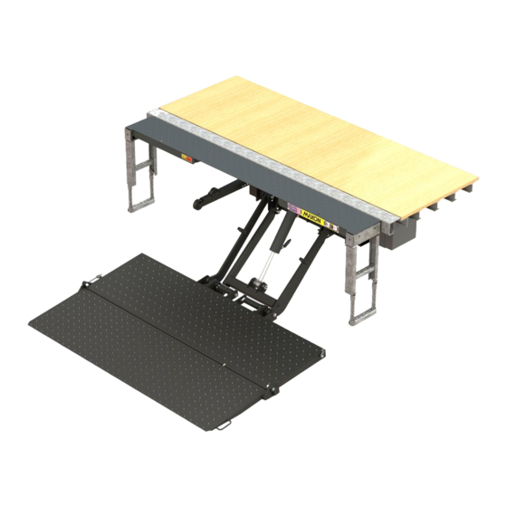
LIFTGATE TERMINOLOGY CONTROL EXTENSION SWITCH PLATE LIFT CYLINDER DOCK BUMPER PLATFORM FLEX STEP OPENER PARALLEL PLATFORM PUMP BOX (COVER SHOWN) MAIN FRAME WEDGE FLIPOVER LIFT FRAME TORSION SPRINGS... -
Page 10: Periodic Maintenance
Check for rust and oily surfaces on Liftgate. If there is rust or oil on Liftgate, clean it off. Touch up the paint or galvanized fi nish where bare metal is showing. MAXON recommends using the aluminum primer touchup paint or cold galvanize spray for galvanized fi nish. -
Page 11: Periodic Maintenance Checklist
To maintain the protection provided by the original paint system or galvanized fi nish, MAXON recommends using the aluminum primer touchup paint or cold galvanize spray for galvanized fi nish. Semi-annually or 2500 Cycles (whichever occurs fi rst) Visually check the platform hinge pins for excessive wear and broken welds. - Page 12 PERIODIC MAINTENANCE PERIODIC MAINTENANCE CHECKLIST - Continued NOTE: Lube fi ttings are shown for the cylinder, LH lift arm, and LH parallel arm. There are also lube fi ttings at the same places on the RH cylinder, lift arm, and parallel arm. Refer to lubrication diagram (FIG.
-
Page 13: Checking Hydraulic Fluid
CHECKING HYDRAULIC FLUID CAUTION Keep dirt, water and other contaminants from entering the hydraulic system. Before opening the hydraulic fl uid reservoir fi ller cap, drain plug and hydrau- lic lines, clean up contaminants that can get in the openings. Also, protect the openings from accidental contamination. - Page 14 PERIODIC MAINTENANCE CHECKING HYDRAULIC FLUID - Continued ISO 32 HYDRAULIC OIL RECOMMENDED PART NUMBER BRANDS CHEVRON HIPERSYN 32 KENDALL GOLDEN MV SHELL TELLUS S2 VX 32 EXXONMOBIL UNIVIS N-32, DTE-24 TABLE 14-1 ISO 15 OR MIL-H-5606 HYDRAULIC OIL RECOMMENDED PART NUMBER BRANDS CHEVRON FLUID A, AW-MV-15...
-
Page 15: Changing Hydraulic Fluid
CHANGING HYDRAULIC FLUID CAUTION Keep dirt, water and other contaminants from entering the hydraulic system. Before opening the hydraulic fl uid reservoir fi ller cap, drain plug and hydrau- lic lines, clean up contaminants that can get in the openings. Also, protect the openings from accidental contamination. - Page 16 PERIODIC MAINTENANCE CHANGING HYDRAULIC OIL - Continued 5. Bolt on the pump cover as shown in FIG. 16-1. Torque the cap screws to 10-14 lb-in. BOLTING PUMP COVER FIG. 16-1...
- Page 17 THIS PAGE INTENTIONALLY LEFT BLANK THIS PAGE INTENTIONALLY LEFT BLANK...
-
Page 18: Platform Adjustment
PERIODIC MAINTENANCE PLATFORM ADJUSTMENT NOTE: Before doing the following procedure, make sure vehicle is parked on level ground. 1. Make sure platform is at ground level. Unfold the platform and fl ipover. As the platform fi rst touches the ground, shackles and tip of fl ipover must touch the ground at the same time (FIG. - Page 19 3. Make shims as needed (FIG. 19-1). Posi- 2-1/4” tion bottom edge of shim to line up with mark on shackle (FIG. 19-2). Then, weld the shim to shackle as shown in FIG. 19-2. 1-1/2” SHIM (1/16”, 1/8”, 3/16”, or 1/4”) MADE FROM STEEL FLAT FIG.
- Page 20 PERIODIC MAINTENANCE PLATFORM ADJUSTMENT - Continued 4. Make sure platform is still at ground level. If the tip of fl ipover is not touching the ground, measure and compare distance “B” (FIG. 20-1) with TABLE 20-1 to determine how TIP OF much to grind from the platform FLIPOVER stops (FIG.
-
Page 21: Replacing Platform Torsion Spring
REPLACING PLATFORM TORSION SPRING 1. Fold fl ipover onto platform. 2. Fold platform. 3. Raise Liftgate to a convenient work height to gain access and release tension on the torsion spring. PLATFORM HINGE PIN FLAT LOCK CAUTION WASHER To prevent injury and equipment dam- age, make sure there is no tension on torsion spring before removing hinge pin. - Page 22 PERIODIC MAINTENANCE REPLACING PLATFORM TORSION SPRING - Continued 6. Drive platform hinge pin inboard to correct position through the platform hinge bracket (FIG. 22-1). Line up FLAT the hole in the platform hinge pin with LOCK WASHER the hole in the pin collar. Reinstall cap screw through the pin collar and secure with fl...
-
Page 23: Safety Hook Maintenance
SAFETY HOOK MAINTENANCE CHECK SAFETY HOOK FUNCTION 1. When raising platform to stowed position, EXTENSION PLATFORM LOOP PLATE listen for sound of safety hook engaging (CORRECT POSITION) platform loop. 2. When the Liftgate is stowed, see if plat- form loop is seated in the safety hook as shown in FIG. -
Page 24: Decals & Plates
DECALS & PLATES NOTE: Ensure there is no residue, dirt or corrosion where decals are attached. If necessary, clean surface before attaching decals. NOTE: Preferred decal layout is shown, Decals on the Liftgate are attached at the factory. If vehicle does not permit this layout, decals in the manual and decal kit must be applied so that they are easily visible when approaching vehicle to operate Liftgate. - Page 25 DECAL SHEET P/N 282522-01 FIG. 25-1 MODEL DECAL P/N CAPACITY TE-15 220386 1500 POUNDS [680 KG] TE-20 220387 2000 POUNDS [907 KG] TE-25 220382 2500 POUNDS [1134 KG] TE-30 220388 3000 POUNDS [1360 KG] CAPACITY DECALS TABLE 25-1...
-
Page 26: Pump, Motor & Solenoid Operation - Gravity Down
SYSTEM DIAGRAMS PUMP, MOTOR & SOLENOID OPERATION - GRAVITY DOWN MOTOR JUNCTION BLOCK PRESSURE SOLENOID SWITCH VENT SOLENOID VALVE GRAVITY DOWN PUMP MOTOR & SOLENOID SWITCH OPERATION SOLENOID SWITCH OPERATION MEANS ENERGIZED) LIFTGATE PORT FUNCTION MOTOR SOLENOID VALVE RAISE PRESSURE LOWER VENT REFER TO VALVES SHOWN ON... -
Page 27: Pump, Motor & Solenoid Operation - Power Down
PUMP, MOTOR & SOLENOID OPERATION - POWER DOWN MOTOR POWER DOWN MODULE PORT A “S2” VALVE SOLENOID SWITCH “S1” VALVE PORT B POWER DOWN PUMP MOTOR & SOLENOID SWITCH OPERATION SOLENOID SWITCH OPERATION MEANS ENERGIZED) LIFTGATE PORT FUNCTION VALVE VALVE POWER DOWN MOTOR “S2”... -
Page 28: Hydraulic System Diagrams
HYDRAULIC SYSTEM DIAGRAMS HYDRAULIC SCHEMATIC (GRAVITY DOWN) HYDRAULIC CYLINDER 2 GPM FLOW CONTROL VALVE RETURN PORT FILLER HOLE (PLUGGED) (PLUGGED) PRESSURE PORT VENT PORT VALVE A RELIEF VALVE CHECK VALVE (SET AT 3250 PSI) AUX. HAND PUMP PORT (PLUGGED) PUMP MOTOR (REFERENCE) FILTER... -
Page 29: Hydraulic Schematic (Power Down)
HYDRAULIC SCHEMATIC (POWER DOWN) HYDRAULIC CYLINDER 2 GPM FLOW CONTROL VALVE PORT B - LOWER PORT A - RAISE (POWER DOWN) RELIEF VALVE 2 (SET AT 1100 PSI) RELIEF VALVE 1 (SET AT 3250 PSI) AUX. HAND PUMP PORT (PLUGGED) MOTOR PUMP (REF) -
Page 30: Electrical System Diagrams
ELECTRICAL SYSTEM DIAGRAMS ELECTRICAL SCHEMATIC (GRAVITY DOWN) CONTROL SWITCH (UP) (DOWN) BLACK GREEN JUNCTION BLOCK WHITE CYCLE COUNTER EQUIPPED) SOLENOID FUSE HOLDER WITH 10 AMP VALVE FUSE CABLE WITH 175 A FUSE STARTER SOLENOID MOTOR BATTERY FIG. 30-1... -
Page 31: Electrical Schematic (Power Down)
ELECTRICAL SCHEMATIC (POWER DOWN) WHITE CONTROL SWITCH (UP) (DOWN) POWER DOWN MODULE BLACK WHITE (CABLE) GREEN BLACK (CABLE) BLACK FUSE HOLDER WITH 10 AMP FUSE SOLENOID, SOLENOID, VALVE S2 VALVE S1 STARTER SOLENOID CABLE WITH 175 A FUSE CYCLE COUNTER MOTOR (IF EQUIPPED) BATTERY... -
Page 32: Te Series Electrical Values
SYSTEM DIAGRAMS TE SERIES ELECTRICAL VALUES Solenoid Switch 5.4Ω @70ºF. ±15% 20.1Ω @70ºF. ±15% Coil Resistance: 2.2A 1.2A Ampere: Coil terminal torque: 10-15 lb-in max. Contact terminal torque: 30-35 lb-in max. Solenoid Valves (A, S1, & S2) 6.6Ω @ 70ºF. ±15% 26.7Ω... -
Page 33: Troubleshooting
TROUBLESHOOTING PLATFORM WILL NOT RAISE 1. Use voltmeter to verify power is being supplied to solenoid terminal “B” (FIG. 33-1). Recharge the battery if there is less than 12.6 volts. CAUTION Keep dirt, water and other contaminants from entering the hydraulic system. Before opening the hydraulic fl... -
Page 34: Platform Raises But Leaks Down
TROUBLESHOOTING PLATFORM RAISES BUT LEAKS DOWN 1. Check if solenoid valves are constantly energized by touching a screwdriver to the top nut of the solenoid COIL (FIG. 34-1). Try pulling the screwdriver away from the solenoid. If the solenoid nut attracts the screwdriver (magnetically) without pushing the toggle switch, the con- trol circuit is operating incorrectly. -
Page 35: Platform Raises Partially And Stops
PLATFORM RAISES PARTIALLY AND STOPS CAUTION Keep dirt, water and other contaminants from entering the hydraulic system. Before opening the hydraulic fl uid reservoir fi ller cap, drain plug and hydraulic lines, clean up contaminants that can get in the openings. Also, protect the openings from accidental contamination during maintenance. -
Page 36: Liftgate Will Not Lift Rated Capacity
TROUBLESHOOTING LIFTGATE WILL NOT LIFT RATED CAPACITY 1. Use voltmeter to verify the battery shows 12.6 volts or more under load from pump motor. 2. Check for structural damage and lack of lubrication. Replace worn parts. CAUTION Keep dirt, water and other contaminants from entering the hydraulic system. Before opening the hydraulic fl... -
Page 37: Platform Raises Slowly
PLATFORM RAISES SLOWLY 1. Use voltmeter to verify power is being supplied to TERMINAL “B” solenoid terminal “B”. Recharge the battery if volt- BATTERY (+) meter indicates less than 12.6 volts (FIG. 37-1). CAUTION Keep dirt, water and other contaminants from entering the hydraulic system. -
Page 38: Platform Will Not Lower, Lowers Too Slowly Or Too Quickly
TROUBLESHOOTING PLATFORM WILL NOT LOWER, LOWERS TOO SLOWLY OR TOO QUICKLY TERMINAL “B” 1. Use voltmeter to verify power is being supplied to BATTERY (+) solenoid terminal “B”. Recharge the battery if volt- meter displays less than 12.6 volts (FIG. 38-1). 2.
Need help?
Do you have a question about the TE-15 and is the answer not in the manual?
Questions and answers