Table of Contents
Advertisement
Advertisement
Table of Contents

Subscribe to Our Youtube Channel
Related Manuals for Maxon TUK-A-WAY LIFTGATE Series


Summary of Contents for Maxon TUK-A-WAY LIFTGATE Series
- Page 1 M-00-41 REV. A MARCH 2002...
- Page 3 Term of Warranty: 2 Years from Date of In-Service Type of Warranty: Full Parts and Labor MAXON agrees to replace any components which are found to be defective during the first 2 years of service, and will reimburse for labor based on MAXON’s Liftgate Warranty Flat Rate Labor Schedule.
-
Page 4: Table Of Contents
TABLE OF CONTENTS WARNINGS ......................... 6 LIFTGATE TERMINOLOGY ....................7 PERIODIC MAINTENANCE CHECKLIST ................8 CHANGING HYDRAULIC FLUID ................... 9 PLATFORM ADJUSTMENT ....................10 REPLACING PLATFORM TORSION SPRING ..............12 SAFETY HOOK MAINTENANCE ..................14 PARTS BREAKDOWN .................. 15 72-25C/30C ASSEMBLY ....................17 MAIN FRAME ASSEMBLY .................... - Page 5 TABLE OF CONTENTS - Continued PLATFORM ASSEMBLY - WEDGE FLIPOVER OPTION ............ 36 GRAVITY DOWN LOW VOLTAGE SWITCH (LVTS) ............37 POWER DOWN LOW VOLTAGE SWITCH (LVTS) ............. 38 TROUBLESHOOTING .................. 39 PLATFORM WILL NOT RAISE .................... 40 PLATFORM RAISES BUT LEAKS DOWN ................41 PLATFORM RAISES PARTIALLY AND STOPS ..............
-
Page 6: Warnings
• Never perform unauthorized modifications on the Liftgate. Modifications may result in early failure of the Liftgate and may create hazards for Liftgate operators and maintainers. • Use only Maxon Authorized Parts for replacement parts. Provide Liftgate model and serial num- ber information with your parts order. Order replacement parts from: MAXON LIFT CORP. -
Page 7: Liftgate Terminology
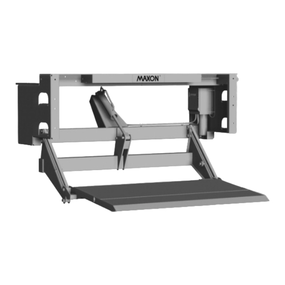
LIFTGATE TERMINOLOGY (72-25C/30C) MTB CONTROL SWITCH PARALLEL LIFT CYLINDER PLATFORM PUMP FLIPOVER ASSEMBLY MAINFRAME ALUMINUM RETENTION RAMP LIFT FRAME PAGE 7... -
Page 8: Periodic Maintenance Checklist
PERIODIC MAINTENANCE CHECKLIST ! ! ! ! ! WARNING Never operate the Liftgate with parts loose or missing. Annually Visually check the entire Liftgate for excessively worn parts and broken welds, especially the Hinge Pins. See PARTS BREAKDOWN section for replacement parts. Also, do the Semi- annual and Quarterly Maintenance checks. -
Page 9: Changing Hydraulic Fluid
CHANGING HYDRAULIC FLUID CAUTION Keep dirt, water and other contaminants from entering the hydraulic system. Before opening the hydraulic fluid reservoir filler cap, drain plug and hydraulic lines, clean up contaminants that can get in the openings. Also, protect the open- ings from accidental contamination. -
Page 10: Platform Adjustment
PLATFORM ADJUSTMENT Open and RAISE Platform to bed level as shown in Operation Manual M-00-40. Platform should be pointing up at bed level and pointing down at ground level (FIG. 2A and FIG. 2B). If the platform is level at bed height (FIG. 2C) and sags at ground level (FIG. - Page 11 THIS PAGE INTENTIONALLY LEFT BLANK PAGE 11...
-
Page 12: Replacing Platform Torsion Spring
REPLACING PLATFORM TORSION SPRING 1. Manually fold Flipover onto Platform as shown in Operation Manual M-00-40. 2. Raise Liftgate to a convenient work height to gain access and release tension on the HAMMER Torsion Spring. CAUTION ! ! ! ! ! To prevent injury and equipment damage, make sure there is no tension on torsion spring before removing hinge pin. - Page 13 5. Drive Platform Hinge Pin into correct position through the Platform Hinge Bracket with a hammer and pin punch as shown in (FIG. 7). Line up the hole in the Platform Hinge Pin with the hole in the Pin Collar. Install the roll pin through the Pin Collar until roll pin protrudes equally from both sides of the collar (FIG.
-
Page 14: Safety Hook Maintenance
SAFETY HOOK MAINTENANCE GREASE FRONT SURFACE OF HOOK WITH AUTOMOTIVE GREASE GREASE ALL HOLES THE ROD PASSES THRU FIG. 8 EXTENSION PLATE CHECK SAFETY HOOK FUNCTION 1. When the Platform is raised to full “Stowed” position, SAFETY HOOK listen for an audible snap when Safety Hook engages the Platform Loop. -
Page 15: Parts Breakdown
PARTS BREAKDOWN PAGE 15... - Page 16 THIS PAGE INTENTIONALLY LEFT BLANK PAGE 16...
-
Page 17: 72-25C/30C Assembly
72-25C/30C ASSEMBLY REFER TO PUMP BOX HYDRUALIC & ELECTRICAL ASSEMBLY REFER TO MAIN FRAME ASSEMBLY REFER TO ARM ASSEMBLY REFER TO PLATFORM ASSEMBLY PAGE 17... -
Page 18: Main Frame Assembly
MAIN FRAME ASSEMBLY VIEWED FROM UNDER EXTENSION PLATE VIEW FROM UNDER EXTENSION PLATE PAGE 18... - Page 19 MAIN FRAME ASSEMBLY T I M T I M T I M T I M 1 1 1 1 1 2 2 2 2 2 3 3 3 3 3 4 4 4 4 4 5 5 5 5 5 6 6 6 6 6 7 7 7 7 7 "...
-
Page 20: Arm Assembly
ARM ASSEMBLY T I M T I M T I M T I M 1 1 1 1 1 2 2 2 2 2 3 3 3 3 3 4 4 4 4 4 5 5 5 5 5 " 2 6 6 6 6 6 7 7 7 7 7 8 8 8 8 8... -
Page 21: Platform Assembly
PLATFORM ASSEMBLY T I M T I M T I M T I M 1 1 1 1 1 2 2 2 2 2 3 3 3 3 3 " 4 4 4 4 4 4 5 5 5 5 5 "... -
Page 22: Hydraulic Components
HYDRAULIC COMPONENTS 6A, 7A PUMP BOX COVER RIGHT HAND SIDE PLATE GRAVITYDOWN (CURB SIDE) -REFERENCE PUMP 6B, 7B POWERDOWN PUMP PAGE 22... - Page 23 HYDRAULIC COMPONENTS T I M T I M T I M T I M 1 1 1 1 1 2 2 2 2 2 " 3 3 3 3 3 " " 4 4 4 4 4 " ° ° 9 9 9 9 9 "...
-
Page 24: Gravity Down Electric Components
GRAVITY DOWN ELECTRIC COMPONENTS PAGE 24... - Page 25 GRAVITY DOWN ELECTRIC COMPONENTS T I M T I M T I M T I M 1 1 1 1 1 2 2 2 2 2 3 3 3 3 3 4 4 4 4 4 5 5 5 5 5 6 6 6 6 6 7 7 7 7 7 8 8 8 8 8...
-
Page 26: Power Down Electric Components
POWER DOWN ELECTRIC COMPONENTS PAGE 26... - Page 27 POWER DOWN ELECTRIC COMPONENTS T I M T I M T I M T I M 1 1 1 1 1 2 2 2 2 2 3 3 3 3 3 4 4 4 4 4 5 5 5 5 5 6 6 6 6 6 7 7 7 7 7 8 8 8 8 8...
-
Page 28: Decals
DECALS CURBSIDE ROADSIDE VIEW VIEW DECAL DECAL P/N 265439 P/N 265438 PAGE 28... -
Page 29: Control Switch And Power Cable
CONTROL SWITCH AND POWER CABLE SWITCH & CABLE SWITCH BOOT SEAL ASSEMBLY P/N 905206 P/N 264346 (For Reference Only) SCREW, SELF-TAPPING #10 X 5/8” P/N 030453 (2 PLACES) NOTE: Use Switch to RAISE and LOWER Liftgate to make sure Switch operates as shown on the decal. -
Page 30: Liquid Sealant Application
LIQUID SEALANT APPLICATION NOTE: Apply Sealant to NPT threads for cylinder and flow control valve only! Clean all threads with a soft brush and a suitable cleaning solvent. Dry threads thoroughly with compressed air or shop towel. Apply the Liquid Sealant (Compound PLS 2), to the external threads of the Male Connector. -
Page 31: Options
OPTIONS PAGE 31... -
Page 32: Platform Assembly (72" X 40" + 10") - Retention Ramp Option
PLATFORM ASSEMBLY (72” x 40” + 10”) - RETENTION RAMP OPTION REFER TO LEFT HAND HINGE ASSY REFER TO RIGHT HAND HINGE ASSY PAGE 32... - Page 33 PLATFORM ASSEMBLY (72” x 40” + 10”) - RETENTION RAMP OPTION T I M T I M T I M T I M 1 1 1 1 1 2 2 2 2 2 3 3 3 3 3 4 4 4 4 4 5 5 5 5 5 "...
-
Page 34: Hinge Assembly, Right Hand
HINGE ASSEMBLY, RIGHT HAND P/N 253877 (REF) (REF) T I M T I M T I M T I M Q . Y 1 1 1 1 1 " 8 " 0 " 9 2 2 2 2 2 3 3 3 3 3 4 4 4 4 4 "... -
Page 35: Hinge Assembly, Left Hand
HINGE ASSEMBLY, LEFT HAND P/N 253876 (REF) (REF) T I M T I M T I M T I M 1 1 1 1 1 " 8 " 0 " 9 2 2 2 2 2 3 3 3 3 3 4 4 4 4 4 5 5 5 5 5 6 6 6 6 6... -
Page 36: Platform Assembly - Wedge Flipover Option
PLATFORM ASSEMBLY - WEDGE FLIPOVER OPTION T I M T I M T I M T I M 1 1 1 1 1 2 2 2 2 2 3 3 3 3 3 " 4 4 4 4 4 4 5 5 5 5 5 "... -
Page 37: Gravity Down Low Voltage Switch (Lvts)
GRAVITY DOWN LOW VOLTAGE SWITCH (LVTS) G/D LVTS ELECTRICAL HARNESS LVTS P/N 280571-01 P/N 905197 GREEN WIRE ASSY P/N 280573-01 BLACK WIRE ASSY P/N 280537-01 STARTER SOLENOID MOTOR MOTOR SWITCH WHITE WHITE LVTS G/D LVTS ELECTRICAL HARNESS TO GROUND ON STARTER SOLENOID BRACKET SOLENOID... -
Page 38: Power Down Low Voltage Switch (Lvts)
POWER DOWN LOW VOLTAGE SWITCH (LVTS) P/D LVTS ELECTRICAL HARNESS P/N 280572-01 LVTS P/N 905197 LVTS 1 BLACK WIRE ASSY P/N 280537-01 LVTS 2 MOTOR MOTOR SWITCH STARTER SOLENOID ELECTRICAL HARNESS P/D LVTS RELAY, 12 VDC NOTE: LVTS-1 “GND” IS CONNECTED TO GROUND ON STARTER SOLENOID-1. -
Page 39: Troubleshooting
TROUBLESHOOTING ......................PAGE 39... -
Page 40: Platform Will Not Raise
PLATFORM WILL NOT RAISE 1. Use voltmeter to verify that power is being supplied to Solenoid Terminal “A”. Recharge the battery if less than 12.6 volts. CAUTION Keep dirt, water and other contaminants from entering the hydraulic system. Before opening the hydraulic fluid reservoir filler cap, drain plug and hydraulic lines, clean up contaminants that can get in the openings. -
Page 41: Platform Raises But Leaks Down
PLATFORM RAISES BUT LEAKS DOWN COIL 1. Check if Solenoid Valves are constantly energized by touch- ing a screwdriver to the top nut of the Solenoid (FIG. 1). Try pulling the screwdriver away from the solenoid. If the solenoid nut attracts the screwdriver (magnetically) without pushing the toggle switch, the control circuit is operating incorrectly. -
Page 42: Platform Raises Partially And Stops
PLATFORM RAISES PARTIALLY AND STOPS CAUTION Keep dirt, water and other contaminants from entering the hydraulic system. Before opening the hydraulic fluid reservoir filler cap, drain plug and hydraulic lines, clean up contaminants that can get in the openings. Also, protect the openings from accidental contamination during maintenance. -
Page 43: Liftgate Will Not Lift Rated Capacity
LIFTGATE WILL NOT LIFT RATED CAPACITY 1. Use voltmeter to verify that the Battery shows 12.6 volts or more under load from pump motor. 2. Check for Structural damage or lack of lubrication.Replace worn parts. CAUTION ! ! ! ! ! Keep dirt, water and other contaminants from entering the hydraulic system. -
Page 44: Platform Raises Slowly
PLATFORM RAISES SLOWLY 1. Use voltmeter to verify that power is being supplied to Solenoid Terminal “A”. Recharge the battery if volt- meter indicates less than 12.6 Volts ( FIG. 6). CAUTION Keep dirt, water and other contaminants from entering the hydraulic system. -
Page 45: Platform Will Not Lower, Lowers Too Slowly, Or Lowers Too Quickly
PLATFORM WILL NOT LOWER, LOWERS TOO SLOWLY, OR LOWERS TOO QUICKLY 1. Use voltmeter to verify that power is being supplied to Solenoid Terminal “A”. Recharge the battery if voltmeter indicates less than 12.6 Volts ( FIG. 9). 2. Check for structural damage or poor lubrication. Replace worn parts.
Need help?
Do you have a question about the TUK-A-WAY LIFTGATE Series and is the answer not in the manual?
Questions and answers