Table of Contents
Advertisement
Quick Links
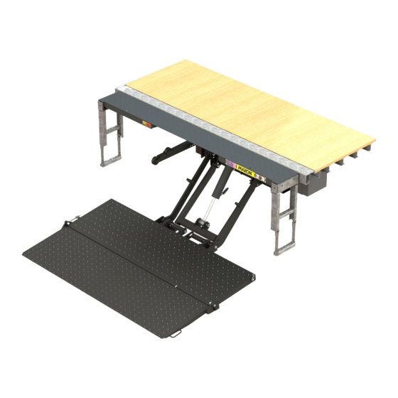
To find maintenance & parts information for your TE-15, TE-20, TE-25 or
TE-30 Liftgate, go to www.maxonlift.com. Click the PRODUCTS, TUK-A-
WAY & TE-15/TE-20, TE-25/TE-30 buttons. Open the Maintenance Manual
in the PRODUCT DOCUMENTATION window. For parts, click on the
PARTS PORTAL, TUK-A-WAY & TE-15/TE-20, TE-25/TE-30 buttons.
M-16-34
REV. A
SEPTEMBER 2017
©
2017 MAXON LIFT CORP.
Advertisement
Table of Contents

Related Manuals for Maxon TE-15


Summary of Contents for Maxon TE-15
- Page 1 M-16-34 REV. A SEPTEMBER 2017 To find maintenance & parts information for your TE-15, TE-20, TE-25 or TE-30 Liftgate, go to www.maxonlift.com. Click the PRODUCTS, TUK-A- WAY & TE-15/TE-20, TE-25/TE-30 buttons. Open the Maintenance Manual in the PRODUCT DOCUMENTATION window. For parts, click on the PARTS PORTAL, TUK-A-WAY &...
-
Page 3: Table Of Contents
TABLE OF CONTENTS SUMMARY OF CHANGES: M-16-34 REV A ......4 WARNINGS ................5 LIFTGATE TERMINOLOGY ...........6 RECOMMENDED DAILY OPERATION CHECKS ....8 DECALS .................11 FORKLIFT ADVISORY ............13 ROADSIDE OPERATION ADVISORY ........14 OPERATION ................15 USING CART STOPS (IF EQUIPPED) ........22... -
Page 4: Summary Of Changes: M-16-34 Rev A
SUMMARY OF CHANGES: M-16-34 REV A PAGE DESCRIPTION OF CHANGE Updated REV, date of release, cover image and Maxon COVER website information. Added TE-15 & TE-20 terminology page. -
Page 5: Warnings
Maxon’s website at www.maxonlift.com. 2. Do not exceed rated load capacity of the Liftgate which is 1500 LB for model TE-15, 2000 LB for TE-20, 2500 LB for TE-25 and 3000 LB for model TE-30. 3. Do not allow any part of your body to be placed under, within, or... -
Page 6: Liftgate Terminology
LIFTGATE TERMINOLOGY TE-15 & TE-20 EXTENSION PLATE LIFT DOCK CYLINDER CONTROL BUMPER SWITCH DUAL STEP PLATFORM OPENER PARALLEL PLATFORM PUMP MAIN FRAME LIFT FRAME TORSION WEDGE FLIPOVER SPRING... - Page 7 LIFTGATE TERMINOLOGY TE-25 & TE-30 EXTENSION PLATE LIFT DOCK CONTROL CYLINDER BUMPER SWITCH FLEX STEP PLATFORM OPENER PARALLEL PLATFORM PUMP MAIN FRAME WEDGE FLIPOVER LIFT FRAME TORSION SPRING...
-
Page 8: Recommended Daily Operation Checks
RECOMMENDED DAILY OPERATION CHECKS NOTE: Before you check the Liftgate, park vehicle on flat ground and set the parking brake. NOTE: If any of the following operation checks reveal a need to service or repair Liftgate, do not operate the Liftgate until a qualified mechanic services or repairs the Liftgate. Before operating the Liftgate, the operator should do the following: ... - Page 9 With the platform at vehicle bed height and no load on platform, outboard edge of platform must be higher than extension plate as shown in the YES illus- tration (FIG. 9-1). If the platform is tilted up like the LEVEL LINE YES illustration, you can...
- Page 10 RECOMMENDED DAILY OPERATION CHECKS - Continued With the platform unfolded and on the ground, check if the shackles and the tip of platform touch the ground at the same time as shown in the YES illus- SHACKLE tration (FIG. 10-1). If the platform TIP OF looks like the YES illustra- FLIPOVER...
-
Page 11: Decals
P/N 282847-02 INSTRUCTION DECAL P/N 285800-01 DECAL “F” DECAL “B” DECAL “A” DECAL “C” FIG. 11-1 WARNING DECAL MODEL DECAL P/N CAPACITY DECAL P/N 265736-03 TE-15 220386 1500 POUNDS TE-20 220387 2000 POUNDS TE-25 220382 2500 POUNDS TE-30 220388 3000 POUNDS... - Page 12 DECAL SHEET P/N 282522-01 FIG. 12-1...
-
Page 13: Forklift Advisory
FORKLIFT ADVISORY WARNING Keep Forklift OFF of Platform. FIG. 13-1... -
Page 14: Roadside Operation Advisory
Liftgate, cargo & vehicle. Making the loading area more visible to passing traffic can help reduce the chance of injury and damage. NOTE: MAXON recommends placing at least 2 traffic cones on the traffic side of the platform loading area as illustrated below. Remove cones after platform is stowed and before moving the vehicle. -
Page 15: Operation
OPERATION 1. Standing to the side of platform (FIG. 15-1), pressurize hydraulic sys- tem by pushing the toggle switch to UP position for 2 seconds (FIG. 15-1A.) FIG. 15-1A PRESSURIZING HYDRAULIC SYSTEM FIG. 15-1 WARNING Never operate control switch while unfolding (and folding) platform and flipover. - Page 16 3. Use handle on bottom of platform (FIG. 16-1A) to unfold the platform and flipover (FIG. 16-1). FIG. 16-1A UNFOLDING PLATFORM & FLIPOVER FIG. 16-1 4. Unhook (if equipped) and unfold the flipover as fol- lows. If equipped with hook, press down on the flipover and rotate hook away from the handle (FIGS.
- Page 17 OPERATION - Continued NOTE: While operating the Liftgate, release toggle switch to stop the platform. 5. Raise the platform (FIG. 17-1) by pushing the toggle switch to the UP position (FIG. 17-1A). If loading (or unloading) the platform, wait a second before releasing the toggle switch, after platform reaches bed height.
- Page 18 WARNING A load should never extend past the edges of the platform. Do not place unstable loads on platform and do not allow load to exceed the lifting capacity of the Liftgate. If standing on platform, do not allow your feet to extend beyond the inboard edge of the platform. 6.
- Page 19 OPERATION - Continued WARNING Pulling the load from vehicle to platform can result in a fall from platform and serious injury. When unloading vehicle, always push the load out on the platform. 8. Load the platform at bed INBOARD height (FIG. 19-1) as fol- EDGE lows.
- Page 20 WARNING Never move the vehicle unless the Liftgate is properly stowed. NOTE: Platform raised off the ground makes it easier to grasp and fold the flipover. 10. Before moving the vehicle, prepare the Liftgate as follows. Make sure load is removed from platform. If FIG.
- Page 21 OPERATION - Continued 12. Use handle on bottom of plat- form (FIG. 21-1A) to lift and fold the platform and flipover (FIG. 21-1). FIG. 21-1A FOLDING PLATFORM & FLIPOVER FIG. 21-1 13. Stow the platform (FIG. 21-2) by pushing the tog- gle switch to the UP posi- tion (FIG.
-
Page 22: Using Cart Stops (If Equipped)
USING CART STOPS (IF EQUIPPED) CAUTION To prevent injuries caused by tripping and falling, make sure cart stops are closed before walking on and off outboard end of platform. NOTE: Some Liftgates are equipped with single or dual cart stops. Cart stops prevent loaded carts from rolling off outboard end of platform. - Page 23 USING CART STOPS (IF EQUIPPED) - Continued NOTE: Cart stops are opened by rotating the hook (FIG. ROTATE TO 23-1B). OPEN 2. Open cart stops (FIGS. 23-1A and 23-1B). Next, position cart and stand in the footprint area as shown in FIG.
- Page 24 WARNING Pulling the load from vehicle to platform can result in a fall from platform and serious injury. When unloading vehicle, always push the load out on the platform. 4. When loading the platform INBOARD EDGE at bed level, make sure cart stops are open (FIG.
Need help?
Do you have a question about the TE-15 and is the answer not in the manual?
Questions and answers