Table of Contents
Advertisement
Quick Links
Advertisement
Table of Contents

Related Manuals for Holemaker Technology VERSADRIVE V125T


Summary of Contents for Holemaker Technology VERSADRIVE V125T
- Page 1 Magnetic Drilling Machine V125T (Original Instructions)
- Page 2 Congratulations on your purchase of the Holemaker Technology VERSADRIVE V125T Transportable Magnetic Drilling Machine. Your model is designed to produce superior holes quickly and efficiently. Through years of experience, constant innovation and development, HMT is committed to provide you with metal cutting tools and products to help you be more productive.
-
Page 3: Table Of Contents
1 Table of contents Table of contents Safety General safety instructions 2.1.1 Work Area 2.1.2 Electrical Safety 2.1.3 Personal Safety 2.1.4 Machine Use and Care 2.1.5 Service Magnetic Drill specific safety information Description Intended use Description and features Packing List Serial number Technical data Environmental... -
Page 4: Safety
2 Safety 2.1 General safety instructions Do not use this power tool before you have thoroughly read and completely understood this Instruction Manual and the “General Safety Instructions”, including the figures, specifications, safety regulations and the signs indicating DANGER, WARNING and CAUTION. WARNING: When using electrical tools basic safety precautions should always be followed to reduce the risk of fire, electrical shock and personal injury including following. -
Page 5: Personal Safety
2.1.3 Personal Safety 1. Stay alert, watch what you are doing and use common sense when using a magnetic drilling machine. Do not use machine while tired or under the influence of drugs, alcohol, or medication. 2. Use personal protective equipment. Always wear eye protection. 3. -
Page 6: Magnetic Drill Specific Safety Information
2.2 Magnetic Drill specific safety information • Keep your fingers well out of the drill/cutter area. • Avoid touching the drilled core that is automatically ejected by the centering pin when the working procedure is finished. Contact with the core when it is hot, or if it falls, can cause personal injuries. -
Page 7: Description
RESIDUAL RISKS In following the relevant safety regulations and the implementation of safety devices, certain residual risks cannot be avoided. These are: • Impairment of hearing • Risk of personal injury from flying particles • Risk of burns due to accessories becoming hot during operation •... -
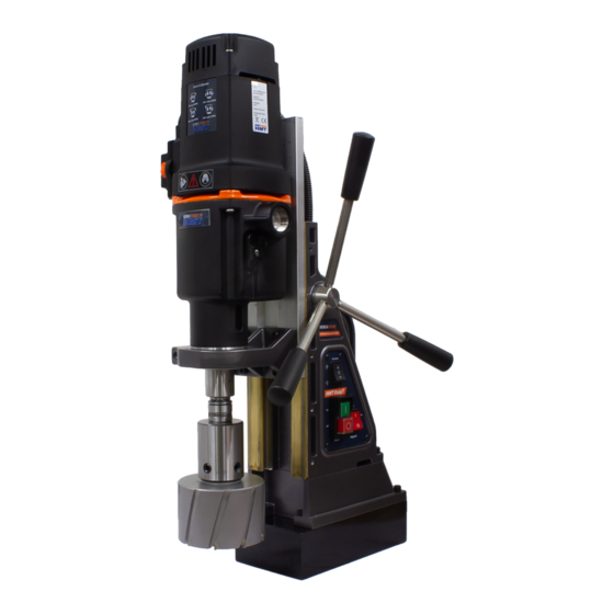
Page 8: Description And Features
3.2 Description and features [image 1] Motor Unit Safety Guard Magnet Feed Handle Stand Carry Handle Coolant Bottle Motor Switch Magnet Switch Direction or Rotation Switch Magnet Protection Fuse Power Cable Outlet Spacer Gear Selector (one each side) V125T/July 2020/V1.1... -
Page 9: Packing List
3.3 Packing List Standard Machine 1 x Magnetic Drilling Machine 1 x Instruction Manual 1 x Standard Weldon Arbor 1 x VERSADRIVE RAPID LOCK Weldon Adaptor 1 x Drill Guard & 2 Thumbscrews 1 x Hex Key (3) 1 x Safety Strap 1 x Drill Drift 1 x Basic Carrying Case 1 x Bottle of Cutting Oil... -
Page 10: Technical Data
3.5 Technical data VERSADRIVE V125T - 110V / 230V (Check machine markings) Capacity Annular Cutters Up to Ø125 mm (TCT cutters) Capacity Twist Drills Ø 1 – 32 mm Capacity Threading Capacity Countersinking Ø 65mm (in S275) Overall Length 350mm (with guard) - Page 11 Symbols Symbol Term, meaning Explanation You MUST read the enclosed documentation such Read Documentation as the Instruction Manual and the General Safety Instructions. Wear ear protection Use ear protection during operation. Wear eye protection Use eye-protection during operation. Wear Gloves Danger/warning/caution Observe the information in the adjacent text! Warning Electrical Enclosure...
-
Page 12: Environmental
3.6 Environmental Separate collection. This product must NOT be disposed of with normal household waste. Separate collection of used products and packaging allows materials to be recycled and used again. Re-use of recycled materials helps prevent environmental pollution and reduces the demand for raw materials. -
Page 13: Preparation & Adjustment
4 Preparation & adjustment 4.1 Assembly WARNING: To reduce the risk of injury, turn unit off and disconnect machine from power source before installing and removing accessories, before adjusting or changing set- ups or when making repairs. Be sure all switches are in the OFF position. An accidental start-up can cause injury. 4.1.1 Fitting the feed handles Take the feed handle (x 3), and screw each one in turn into the pinion shaft. - Page 14 To remove the feed handle from the machine, first lower the slide until it is at its lower most position. Unscrew the M6 cap screw (item 1) and remove the pinion shaft retainer (item 2). The pinion shaft and feed handle assembly (item 3) can now be withdrawn. [image 3] It is possible to position the feed handle on either side of the machine (image 4).
-
Page 15: Mounting The Drill Guard
4.1.2 Mounting the drill guard The drill guard protects against ejection of sharp and/or hot chippings, it also protects against accidental contact with rotating parts and must always ALWAYS be mounted during operation. 1) Ensure the drill mounting bracket (1) is attached to the motor lower support and is secure. 2) Slide the drill guard (2) up to the bracket. -
Page 16: Fitting The Cooling System
4.1.3 Fitting the cooling system Description of the cooling system. The coolant system consists of the following items:- 1. Coolant bottle 2. Flow adjustment tap 3. Coolant tube 4. MT3 Arbor with integral coolant collar 5. Stay Bar The coolant system has a cutter holder (4) with an integral collar which allows coolant to be fed down through the centre of the cutter whilst rotating. - Page 17 Fitting the coolant system – Fit the coolant arbor by engaging the morse taper of the arbor into the drill units morse taper socket. The stay bar must be aligned to fit into one of the two slots in the motor support bracket. See image 7 –...
- Page 18 Fit the coolant tube to both the coolant bottle and the cutter holder. [image 9] To regulate the flow of coolant, rotate the tap at the bottom of the coolant bottle [image 10] V125T/July 2020/V1.1...
-
Page 19: Fitting The Safety Strap
4.1.4 Fitting the safety strap The safety strap should always be used during operation. Use of the safety strap reduces the risk of personal injury if for some reason there is a loss of magnetic adhesion and the magnet comes loose from the workpiece (such as loss of power supply). The purpose of the safety strap is to prevent the machine from falling or spinning should there be a loss of magnetic adhesion. -
Page 20: Prior To Use
4.2 Prior to use Please make sure that the contacting surface for the magnet is level, clean and rust-free. Remove any varnish or primer. When working on materials that are not magnetizable, suitable fixation devices are obtainable as accessories from HMT, e. g. suction plate, vacuum plate or pipe-drilling clamp must be used. -
Page 21: Using The Machine
5 Using the machine WARNING: Always observe the safety instructions and applicable regulations. WARNING: To reduce the risk of serious personal injury, turn tool off and disconnect tool from power source before making any adjustments or removing/installing attachments or accessories. 5.1 Carrying handle This machine has an integral carrying handle built into the stand housing. -
Page 22: Control Panel
5.2 Control panel The control panel on your magnetic drilling machine is designed for maximum operating safety. 1. Magnet Switch (Illuminated) 2. Motor NVR Switch 3. Spindle Direction Switch 4. Magnet Protection Fuse (2A Fast Blow) [image 13] 5.2.1 Magnet Switch The magnet switch (Image 13 - item 1) is an illuminated rocker switch. -
Page 23: Motor Nvr Switch
5.2.2 Motor NVR Switch The Motor NVR Switch (image 13 – item 2) operates the motor spindle. NVR = No Volt Release – The motor switch has an undervoltage release mechanism to switch off the motor if the supply voltage reduces. The switch must be manually reset when the power is retuned, this is a safety feature. -
Page 24: Speed And Torque Control
5.3 Speed and Torque Control SPEED CONTROL The VERSADRIVE V125T has both Mechanical and Electronic Speed and Torque control. The mechanical speed control is by 2 sliding speed selector, with 1 positioned on either side of the motor gearbox. The mechanical speed position should be set first, choosing the lowest gear ratio will provide the best torque. - Page 25 The speed ranges are shown in the table below. min-1 Left Gear Selector Right Gear Selector Speed Range Position Position 60-140 Position Position 100-220 Position Position 140-310 Position Position 210-490 V125T/July 2020/V1.1...
- Page 26 TORQUE / POWER BOOST CONTROL In addition to the Electronic Speed Control, the VERSADRIVE V125T has a Torque / Power Boost Control. This control is primarily for situations where the Electronic Speed Control is at a low position or slow speed and extra Torque or Power is required.
-
Page 27: Electro-Magnet
5.4 Electro-Magnet Make sure the magnetic drilling machine is placed on a smooth, clean, level and solid surface without any objects or debris in between to guarantee maximum adhesion. The workpiece must be at least 10 mm thick for the magnet to sufficient to operate the machine. When cutting thin material, it is possible to enhance magnetic adhesion by temporarily adding a piece of similar material to the workpiece on underside to increase the total thickness. -
Page 28: Emergency Stop
It is the responsibility of the operator to make sure the workpiece offers the best basis for the magnetic drilling machine to adhere and that the machine is secure before use. 1) Place the machine on the workpiece 2) Connect the machine to the power supply 3) Position the machine in the exact desired spot 4) Press the red magnet switch to activate the magnet, the magnet switch will illuminate. -
Page 29: Tool Lubrication
5.6 Tool lubrication MACHINE IN UPRIGHT DRILLING POSITION In order to use the lubrication system, the tank must be filled with a cutting fluid or oil 1) Make sure the flow regulator is closed. 2) Unscrew the fluid reservoir cap. 3) Fill the fluid reservoir with cutting fluid or oil. -
Page 30: Working With Operating Tools
6.1 The Morse Taper arbor FITTING THE MORSE TAPER ARBOR The standard VERSADRIVE V125T machine is supplied with a standard MT3 to Weldon arbor. To fit a morse taper arbor into the machine: 1. Ensure the machine is unplugged from the supply. - Page 31 REMOVING THE MORSE TAPER ARBOR To remove the morse taper arbor from the machine: 1. Ensure the machine is unplugged from the supply. 2. Turn the spindle by hand to align the spindle slot with the gearbox housing slot. 3. Insert the drill drift supplied. 4.
-
Page 32: Versadrive Magnet Drill System
6.2 VERSADRIVE Magnet Drill System 1. Morse Taper to 19.05mm (3/4”) Weldon Arbor (Coolant Version Optional). 2. VERSADRIVE RAPID LOCK Morse Taper Adaptor. 3. CARBIDEMAX TCT Broach Cutter. 4. VERSADRIVE RAPID LOCK Weldon Shank Adaptor. (Supplied) 5. VERSADRIVE Clutched Tapping Chuck. 6. -
Page 33: Annular Cutters
VERSADRIVE RAPID LOCK ADAPTORS The VERSADRIVE V125T is supplied as standard with a VERSADRIVE RAPID LOCK Weldon adaptor. The VERSADRIVE RAPID LOCK Weldon adaptor can also be used to adapt other magnetic drill. This adaptor fits directly into the Weldon arbor of the machine to allow rapid loading of all VERSADRIVE tools/cutters. - Page 34 DRILLING CONDITIONS The ease with which material can be drilled depends on several factors such as the tensile strength and hardness. Whilst hardness and/or strength is the usual criterion, wide variations in machinability can exist among material showing similar physical properties. The drilling conditions are dependent on requirements for tool life and surface finish.
- Page 35 Insert the cutter and pin into the machine arbor, ensure both of the cutter shank flats align with the fixing screws on the machine arbor. Once the cutter is aligned and pressed fully home tighten the two Allen screws with the key supplied. ALWAYS MAKE SURE THE POWER PLUG IS DISCONNECTED! [image 18] Standard Arbor - Guard not shown for clarity.
- Page 36 7. Use the feed handle to lower the cutter to the workpiece, begin with relatively light pressure until a groove is formed. 8. Apply a regular pressure while drilling. The drilling performance does not improve by putting more pressure on the tool. Too much pressure will overload and slow the motor and as a result your annular cutter will become worn sooner.
-
Page 37: Twist Drills
6.4 Twist drills This magnetic drilling machine can be used with twist drills of the following types. 1) HMT VERSADRIVE shank drills – using the VERSADRIVE Rapid Lock Weldon Adaptor. 2) HMT Weldon shank drills – fitted directly into the Weldon arbor. 3) Morse taper shank drills up to MT3 –... -
Page 38: Maintenance
7 Maintenance Your HMT power tool has been designed to operate over a long period of time with a minimum of maintenance. Continuous satisfactory operation depends upon proper tool care and regular cleaning. CAUTION: To reduce the risk of injury, turn unit off and disconnect machine from power source before installing and removing accessories, before adjusting or changing set- ups or when making repairs. - Page 39 CHECK GEARBOX GREASE The gearbox grease should be checked and replaced at least once a year to ensure maximum lubrication and cooling, and thus the best performance and durability of the machine. CHECK ARMATURE This should be checked at least once per month to check that there are no visual signs of damage to the body or to the commutator.
- Page 40 To adjust the slide 1) Lower the slide to its lowest point 2) Adjust each of the 5x screws, in turn as below. 3) Refer to [image 20]. Release the locknut with an 8mm spanner. 4) Adjust (tighten) the socket set screw with a 2.5mm Allen key. 5) Check the slide movement and keep readjusting until there is a slight resistance.
-
Page 41: Trouble Shooting
8 Trouble shooting Magnet and motor do not function - The machine is not connected to the power supply - Damaged or defective wiring - Defective fuse - Defective magnet switch - Defective power supply Magnet does function, the motor - Damaged or defective wiring does not work - Carbon brushes are stuck or worn out... -
Page 42: Exploded Views & Spare Part Lists
9 Exploded views & Spare part lists 9.1 Motor exploded view VERSADRIVE V125T – Drill unit parts diagram Description HMT Part VERSADRIVE V125T Motor Unit - 110V 859202-110 VERSADRIVE V125T Motor Unit - 230V 859202-230 V125T/July 2020/V1.1... -
Page 43: Motor Spare Part List
9.2 Motor spare part list VERSADRIVE V125T – Motor / Gearbox Parts List Item Description HMT Part Qty Item Description HMT Part Rotor Complete - 230V Disc Rotor Complete - 110V Bearing 6005 2RS Stator Complete - 230V Circlip 47/1.75... -
Page 44: Stand Exploded View
9.3 Stand exploded view VERSADRIVE V125T – Magnetic stand parts diagram V125T/July 2020/V1.1... - Page 45 VERSADRIVE V125T – Magnetic Drill Stand - Parts List Item Description HMT Part Item Description HMT Part Body Casting 859001-01 Varistor - 110V 859307-110 Magnet Base (Large) 859101-01 Varistor - 230V 859307-230 Slide (V85T/V125T) 859002-02 X2 Capacitor 859306-01 Lower Support Casting...
-
Page 46: Wiring Diagrams
9.4 Wiring diagrams VERSADRIVE V125T – 230V wiring diagram (below) VERSADRIVE V125T -110V wiring diagram (below) V125T/July 2020/V1.1... -
Page 47: Hmt Warranty Statement
10 HMT Warranty Statement Magnetic Drills & Electrical Equipment HoleMaker Technology warrants its Magnetic Drills for the period stated in the manual or on the product specification sheet which can be found on the website. The warranty period is valid from the date of purchase against defects due to faulty material or workmanship. -
Page 48: Certification
11 Certification Declaration of conformity Holemaker Technology Ltd Bridge House Pattenden Lane Marden Kent TN12 9QJ Declares that the following appliance complies with all relevant CE marking Directive requirements: Product Magnetic Drilling Machine Model VERSADRIVE V125T Ratings and principal characteristics...
Need help?
Do you have a question about the VERSADRIVE V125T and is the answer not in the manual?
Questions and answers