
Related Manuals for Dell EMC Latitude 5511


Summary of Contents for Dell EMC Latitude 5511
- Page 1 Dell Latitude 5511 Setup and specifications guide Regulatory Model: P80F Regulatory Type: P80F004...
- Page 2 Notes, cautions, and warnings NOTE: A NOTE indicates important information that helps you make better use of your product. CAUTION: A CAUTION indicates either potential damage to hardware or loss of data and tells you how to avoid the problem. WARNING: A WARNING indicates a potential for property damage, personal injury, or death.
-
Page 3: Table Of Contents
Contents 1 Set up your Latitude 5511......................5 2 Create a USB recovery drive for Windows..................7 3 Chassis overview..........................8 Display view.................................... 8 Left view....................................9 Right view....................................9 Bottom view..................................10 Palmrest view..................................11 4 Technical specifications......................12 Processors.....................................12 Chipset....................................12 Operating system................................. 12 Memory.................................... - Page 4 7 System setup..........................28 Boot menu.................................... 28 Navigation keys..................................28 Boot Sequence..................................29 System setup options................................. 29 General options................................29 System information............................... 30 Video....................................31 Security................................... 32 Secure boot..................................33 Intel Software Guard Extensions..........................33 Performance...................................34 Power management..............................34 POST behavior................................35 Manageability.................................
-
Page 5: Set Up Your Latitude 5511
Set up your Latitude 5511 NOTE: The images in this document may differ from your computer depending on the configuration you ordered. 1. Connect the power adapter and press the power button. NOTE: To conserve battery power, the battery might enter power saving mode. Connect the power adapter and press the power button to turn on the computer. - Page 6 4. Create recovery drive for Windows. NOTE: It is recommended to create a recovery drive to troubleshoot and fix problems that may occur with Windows. For more information, see Create a USB recovery drive for Windows. Set up your Latitude 5511...
-
Page 7: Create A Usb Recovery Drive For Windows
Create a USB recovery drive for Windows Create a recovery drive to troubleshoot and fix problems that may occur with Windows. An empty USB flash drive with a minimum capacity of 16 GB is required to create the recovery drive. NOTE: This process may take up to an hour to complete. -
Page 8: Chassis Overview
Chassis overview Topics: • Display view • Left view • Right view • Bottom view • Palmrest view Display view 1. Microphone 2. Camera shutter 3. IR camera (Optional) 4. Camera 5. Camera status light 6. Microphone 7. LCD panel 8. -
Page 9: Left View
Left view 1. Power connector port 2. USB Type-C 3.2 Gen 2 port with DisplayPort 1.4 port/Power Delivery/Thunderbolt 3. USB 3.2 Gen 1 port 4. Fan vents 5. Smart card reader (optional) Right view 1. microSD card reader 2. micro-SIM card slot 3. -
Page 10: Bottom View
Bottom view 1. Fan vents 2. Service tag label 3. Speakers Chassis overview... -
Page 11: Palmrest View
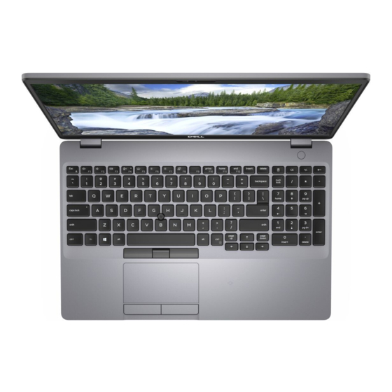
Palmrest view 1. Power button with optional fingerprint reader (FPR) 2. Keyboard 3. NFC/Contactless smart card reader (Optional) 4. Touchpad 5. Pointstick Chassis overview... -
Page 12: Technical Specifications
Technical specifications Processors Table 2. Processors Description Values Processors 10th Generation Intel Core 10th Generation Intel Core 10th Generation Intel Core i5-10300H i5-10400H i7-10850H Wattage 35 W 35 W 35 W Core count Thread count Speed Up to 4.5 GHz Up to 4.6 GHz Up to 5.1 GHz Cache... -
Page 13: System Board Connectors
Description Values Speed 2933 MHz Maximum memory 64 GB Minimum memory 4 GB Configurations supported • 4 GB DDR4 at 2933 MHz (1 x 4 GB) • 8 GB DDR4 at 2933 MHz (2 x 4 GB) • 8 GB DDR4 at 2933 MHz (1 x 8 GB) •... -
Page 14: Audio
Description Values • Micro Secure Digital High Capacity (mSDHC) • Micro Secure Digital Extended Capacity (mSDXC) Audio Table 8. Audio specifications Description Values Controller Realtek ALC3204 with Waves MaxxAudio Pro Stereo conversion 24-bit DAC (Digital-to-Analog) and ADC (Analog-to-Digital) Internal interface Intel HDA (high-definition audio) External interface Universal audio jack... -
Page 15: Communications
Description Values Video 1280 x 720 (VGA/HD) at 30 fps Diagonal viewing angle 78.6 degrees Communications Ethernet Table 12. Ethernet specifications Description Values Model number Intel 1219-V/Intel 1219-LM Gigabit Ethernet controller Transfer rate 10/100/1000 Mbps Wireless module Table 13. Wireless module specifications Description Values Model number... -
Page 16: Power Adapter
Power adapter Table 15. Power adapter specifications Description Values Type 90 W 90 W Type-C 130 W Type-C Diameter (connector) 7.4 mm Type-C connector Type-C connector Input voltage 100 VAC to 240 VAC 100 VAC to 240 VAC 100 VAC to 240 VAC Input frequency 50 to 60 Hz 50 to 60 Hz... - Page 17 Description Values Operating time Varies depending on Varies depending on Varies depending on Varies depending operating conditions and operating conditions and operating conditions and on operating can significantly reduce can significantly reduce can significantly reduce conditions and under certain power- under certain power- under certain power- can significantly...
-
Page 18: Dimensions And Weight
Description Values Coin-cell battery CR2032 CR2032 CR2032 CR2032 Operating time Varies depending on Varies depending on Varies depending on Varies depending operating conditions and operating conditions and operating conditions and on operating can significantly reduce can significantly reduce can significantly reduce conditions and under certain power- under certain power-... -
Page 19: Touchpad
Table 19. Internal ports and connectors Description Values Internal: One M.2 Key-M (2280 or 2230) for solid-state drive • One M.2 2230 slot for solid-state drive 128 GB/256 GB/512 One M.2 2230 Key-E for WLAN • One M.2 2280 slot for solid-state drive 256 GB/512 Gb/1 TB •... -
Page 20: Display
Display Table 22. Display specifications Description Values Type High Definition (HD) Full High Definition (FHD) Full High Definition (FHD) Full high Definition (FHD) Panel technology Wide Viewing Angle (WVA) Wide Viewing Angle Wide Viewing Angle Wide Viewing Angle (WVA) (WVA) (WVA) Luminance (typical) 220 nits... -
Page 21: Fingerprint Reader In Power Button
Feature Specifications • X= 18.6 mm (0.73 in.) key pitch • Y= 19.05 mm (0.75 in.) key pitch Backlit keyboard Optional (backlit and Non-backlit) Layout QWERTY Fingerprint reader in Power Button Table 24. Fingerprint reader specifications Description Values Sensor technology Capacitive Capacitive Sensor resolution... -
Page 22: Security Options-Contactless Smartcard Reader
Title Description Dell ControlVault 3 Smartcard reader ISO 7816 -2 Compliant Specification for smartcard device physical characteristics (size, location of connection points, etc.) T=0 support Cards support character level transmission T=1 support Cards support block level transmission EMVCo Compliant Compliant with EMVCo (for electronic payment standards) smartcard standards as posted to www.emvco.com EMVCo Certified... -
Page 23: Security
Title Description Dell ControlVault 3 Contactless Smartcard reader with NFC EMVCo Certified Formally certified based on EMVCO smartcard standards NFC Proximity OS Interface Enumerates NFP (Near Field Proximity) device for OS to utilize PC/SC OS interface Personal Computer/Smart Card specification for integration of hardware readers into personal computer environments CCID driver compliance... -
Page 24: Security Software
Security Software Table 31. Security Software specifications Specifications Dell Client Command Suite Optional Dell Data Security and Management Software • Dell Client Command Suite • Dell BIOS Verification • Optional Dell Endpoint Security and Management Software • VMware Carbon Black Endpoint Standard •... -
Page 25: Keyboard Shortcuts
Keyboard shortcuts NOTE: Keyboard characters may differ depending on the keyboard language configuration. Keys that are used for shortcuts remain the same across all language configurations. Some keys on your keyboard have two symbols on them. These keys can be used to type alternate characters or to perform secondary functions. - Page 26 Table 34. List of keyboard shortcuts Function key Behavior Pause/Break Sleep Toggle scroll lock Toggle between power and battery-status light/hard-drive activity light System request Open application menu Click Fn-key lock Page up Page down Home Keyboard shortcuts...
-
Page 27: Software
Software This chapter details the supported operating systems along with instructions on how to install the drivers. Topics: • Downloading Windows drivers Downloading Windows drivers 1. Turn on the notebook. 2. Go to Dell.com/support. 3. Click Product Support, enter the Service Tag of your notebook, and then click Submit. NOTE: If you do not have the Service Tag, use the auto detect feature or manually browse for your notebook model. -
Page 28: System Setup
System setup CAUTION: Unless you are an expert computer user, do not change the settings in the BIOS Setup program. Certain changes can make your computer work incorrectly. NOTE: Before you change BIOS Setup program, it is recommended that you write down the BIOS Setup program screen information for future reference. -
Page 29: Boot Sequence
Keys Navigation Moves to the previous page until you view the main screen. Pressing Esc in the main screen displays a message that prompts you to save any unsaved changes and restarts the system. Boot Sequence Boot sequence enables you to bypass the System Setup–defined boot device order and boot directly to a specific device (for example: optical drive or hard drive). -
Page 30: System Information
Option Description Date/Time Allows you to set the date and time settings. Changes to the system date and time take effect immediately. System information Table 36. System Configuration Option Description Integrated NIC Allows you to configure the on-board LAN controller. •... -
Page 31: Video
Option Description • Disabled • • Bright-enabled by default Keyboard Backlight Timeout on The Keyboard Backlight Timeout dims out with AC option. The main keyboard illumination feature is not affected. Keyboard Illumination will continue to support the various illumination levels. This field has an effect when the backlight is enabled. -
Page 32: Security
Security Table 37. Security Option Description Admin Password Allows you to set, change, and delete the admin password. System Password Allows you to set, change, and delete the system password. Internal HDD-2 Password This option lets you set, change, or delete the password on the system's internal hard disk drive (HDD). -
Page 33: Secure Boot
Option Description Admin Setup Lockout Allows you to prevent users from entering Setup when Admin password is set. This option is not set by default. Master Password Lockout Allows you to disable master password support Hard Disk passwords need to be cleared before the settings can be changed. -
Page 34: Performance
Option Description Enclave Memory Size This option sets SGX Enclave Reserve Memory Size Click one of the following options: • 32 MB • 64 MB • 128 MB—Default Performance Table 40. Performance Option Description Multi Core Support This field specifies whether the process has one or all cores enabled. -
Page 35: Post Behavior
Option Description • Every Day • Weekdays • Select Days Default setting: Disabled USB Wake Allows you to enable USB devices to wake the system from Standby. Support NOTE: This feature is only functional when the AC power adapter is connected. If the AC power adapter is removed during Standby, the system setup removes power from all the USB ports to conserve battery power. -
Page 36: Manageability
Option Description Fn Lock Options Allows you to let hot key combinations Fn + Esc toggle the primary behavior of F1–F12, between their standard and secondary functions. If you disable this option, you cannot toggle dynamically the primary behavior of these keys. -
Page 37: Wireless
Wireless Option Description Wireless Device Allows you to enable or disable the internal wireless devices. Enable • WLAN • Bluetooth All the options are enabled by default. Maintenance screen Option Description Service Tag Displays the Service Tag of your computer. Asset Tag Allows you to create a system asset tag if an asset tag is not already set. -
Page 38: Updating Bios On Systems With Bitlocker Enabled
3. If you are unable to detect or find the Service Tag, click Choose from all products. 4. Choose the Products category from the list. NOTE: Choose the appropriate category to reach the product page. 5. Select your computer model and the Product Support page of your computer appears. 6. -
Page 39: System And Setup Password
Figure 1. DOS BIOS Update Screen System and setup password Table 41. System and setup password Password type Description System password Password that you must enter to log on to your system. Setup password Password that you must enter to access and make changes to the BIOS settings of your computer. -
Page 40: Deleting Or Changing An Existing System Setup Password
Deleting or changing an existing system setup password Ensure that the Password Status is Unlocked (in the System Setup) before attempting to delete or change the existing System and Setup password. You cannot delete or change an existing System or Setup password, if the Password Status is Locked. To enter the System Setup, press F2 immediately after a power-on or reboot. -
Page 41: Getting Help
Getting help Topics: • Contacting Dell Contacting Dell NOTE: If you do not have an active Internet connection, you can find contact information on your purchase invoice, packing slip, bill, or Dell product catalog. Dell provides several online and telephone-based support and service options. Availability varies by country and product, and some services may not be available in your area.
Need help?
Do you have a question about the Latitude 5511 and is the answer not in the manual?
Questions and answers