
Related Manuals for Measurement Computing USB-1808X-OEM


Summary of Contents for Measurement Computing USB-1808X-OEM
- Page 1 USB-1808X-OEM Eight-Channel Simultaneous-Sampling Multifunction Device User's Guide May 2019. Rev 4 © Measurement Computing Corporation...
- Page 2 Other product and company names mentioned herein are trademarks or trade names of their respective companies. © 2019 Measurement Computing Corporation. All rights reserved. No part of this publication may be reproduced, stored in a retrieval system, or transmitted, in any form by any means, electronic, mechanical, by photocopying, recording, or otherwise without the prior written permission of Measurement Computing Corporation.
-
Page 3: Table Of Contents
What you will learn from this user's guide ......................5 Conventions in this user's guide ......................... 5 Where to find more information ......................... 5 Chapter 1 Introducing the USB-1808X-OEM ......................6 Functional block diagram ........................... 6 Chapter 2 Installing the USB-1808X-OEM ......................7 Unpacking................................ - Page 4 USB-1808X-OEM User's Guide Noise performance ................................19 Analog output ..............................20 Analog input/output calibration ........................21 Digital input/output............................21 Counter ................................22 Quadrature inputs ................................22 Timer ................................23 External clock input/output..........................23 External trigger ..............................24 Pattern trigger ..............................24 Memory ................................24 Power ................................
-
Page 5: Preface
Preface About this User's Guide What you will learn from this user's guide This user's guide describes the Measurement Computing USB-1808X-OEM data acquisition device and lists device specifications. Conventions in this user's guide For more information Text presented in a box signifies additional information and helpful hints related to the subject matter you are reading. -
Page 6: Introducing The Usb-1808X-Oem
The device is powered by the +5 V USB supply from the computer, requiring no external power. The USB-1808X-OEM is a USB 2.0 high-speed device that is fully compatible with both USB 1.1, USB 2.0, and USB 3.0 ports. -
Page 7: Installing The Usb-1808X-Oem
USB-1808X-OEM. Install the software before you install your device The driver needed to run the USB-1808X-OEM is installed with the software. Therefore, you need to install the software package you plan to use before you install the hardware. Installing the hardware To connect the USB-1808X-OEM to your system, connect the USB cable to an available USB port on the computer or to an external USB hub connected to the computer. -
Page 8: Functional Details
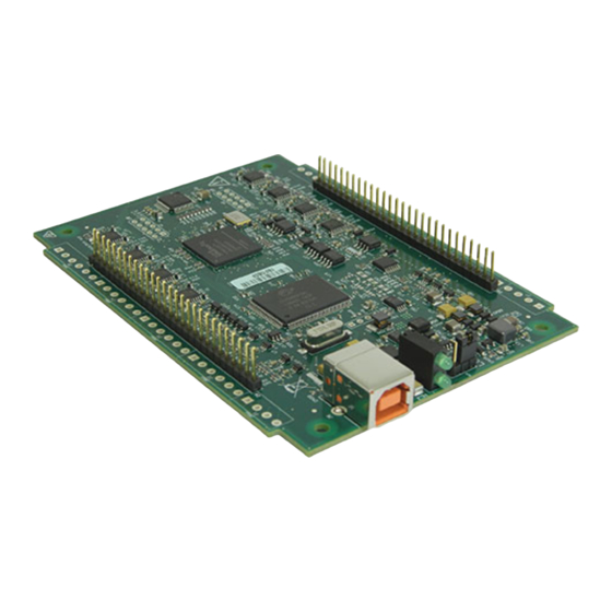
Chapter 3 Functional Details Board components USB-1808X-OEM has the following components, as shown in Figure 2: Header connectors (2) Pull-up/down jumper LED indicators (2) USB connector Figure 2. USB-1808X-OEM components Header connector pins 1 to 28... -
Page 9: Header Connectors
) connection Ten analog ground ( ) and seven digital ground ( ) connections AGND The USB-1808X-OEM pinouts are shown below. Refer to Figure 2 on page 8. Differential mode pinout Terminal Label Label CH0H AI channel 0 HI... -
Page 10: Leds
Encoder 0 Input Z LEDs The USB-1808X-OEM has two LED indicators that indicate the status of power and data. The LEDs are stacked one above the other (see Figure 2 on page 8). LED turns on when the device is detected by the computer. -
Page 11: Channel-Gain Queue
USB-1808X-OEM User's Guide Functional Details Channel-Gain queue The channel-gain queue feature allows you to configure a different gain setting for each channel. The gain settings are stored in a channel-gain queue list that is written to local memory on the device. -
Page 12: Pull-Up/Down Configuration
Turn the device over and rest the top of the housing on a flat, stable surface. Caution! The discharge of static electricity can damage some electronic components. Before removing the USB-1808X-OEM from its housing, ground yourself using a wrist strap or touch the computer chassis or other grounded object to eliminate any stored static charge. -
Page 13: Counter Input
Totalize counter mode The USB-1808X-OEM can be used as a high-speed pulse counter for general counting applications. The internal counter increments when the TTL levels transition from low to high or from high to low. -
Page 14: Quadrature Encoder Input
50 MHz maximum pulse frequency, and X1, X2, and X4 count modes are supported. The USB-1808X-OEM provides A, B, and Z inputs – ENCxA, ENCxB, and ENCxZ – for each connected encoder. A typical encoder generates the A and B signals at a 90° phase shift with respect to each other. These signals are used to determine system position (counts), velocity (counts per second), and direction of travel or rotation. -
Page 15: Synchronous I/O - Mixing Analog, Digital, And Counter Scanning
Synchronous I/O – mixing analog, digital, and counter scanning The USB-1808X-OEM can read analog, digital, and counter inputs, and generate up to two analog outputs and one digital pattern output at the same time. Digital and counter inputs do not affect the overall A/D rate because these inputs use no time slot in the scanning sequencer. -
Page 16: Ground
USB-1808X-OEM User's Guide Functional Details In Figure 7 all mask bits are set to 1, so all the bits are included in the pattern to detect. Figure 7. Trigger mask with all bits included In Figure 8 all mask bits are excluded except bit 3. The result of this operation is that only bit 3 is included in the pattern to detect. -
Page 17: Mechanical Drawings
USB-1808X-OEM User's Guide Functional Details Mechanical drawings Figure 9. USB-1808X-OEM circuit board dimensions... -
Page 18: Specifications
Chapter 4 Specifications All specifications are subject to change without notice. Typical for 25 °C unless otherwise specified. Specifications in italic text are guaranteed by design. Analog input Table 1. General analog input specifications Parameter Condition Specification A/D converter type Simultaneous ADC resolution 18 bits... -
Page 19: Accuracy
USB-1808X-OEM User's Guide Specifications Accuracy Analog input DC voltage measurement accuracy Table 2. DC accuracy components and specifications. All values are (±) Absolute Gain Offset Gain error accuracy at temperature temperature (% of Offset error INL error Full Scale coefficient... -
Page 20: Analog Output
USB-1808X-OEM User's Guide Specifications Analog output Table 5. Analog output specifications Parameter Condition Specification Number of channels Resolution 16 bits Output ranges Calibrated ±10 V Output transient Host computer is reset, powered on, Duration: 5 ms suspended, or a reset command is issued... -
Page 21: Analog Input/Output Calibration
USB-1808X-OEM User's Guide Specifications Analog input/output calibration Table 9. Analog I/O calibration specifications Parameter Specification Warm-up time 15 minutes recommended min Calibration method Factory calibration Calibration interval 1 year Digital input/output Table 10. Digital I/O specifications Parameter Specification Digital type... -
Page 22: Counter
USB-1808X-OEM User's Guide Specifications Counter Table 11. Counter specifications Parameter Specification Terminal names CTR0, CTR1 Number of channels 2 channels Resolution 32-bit Counter type FPGA Counter input modes Totalize, Pulse width, Period Input type Schmitt trigger, 33 Ω series resistor, 47 kΩ pull-down to ground... -
Page 23: Timer
USB-1808X-OEM User's Guide Specifications Timer Table 13. Timer specifications Parameter Specification Terminal name TMR0, TMR1 Timer type PWM output with count, period, delay, and pulse width registers Output value Default state is idle low with pulses high, software-selectable output invert... -
Page 24: External Trigger
USB-1808X-OEM User's Guide Specifications External trigger Table 15. External trigger specifications Parameter Specification Trigger source ITRIG for inputs, OTRIG for outputs Trigger mode Software programmable for edge or level sensitive, rising or falling edge, high or low level. Power on default is edge sensitive, rising edge. -
Page 25: Usb
USB-1808X-OEM User's Guide Specifications Table 19. USB specifications Parameter Specification USB device type USB 2.0 (high-speed) Device compatibility USB 1.1, USB 2.0, USB 3.0 USB cable type A-B cable, UL type AWM 2725 or equivalent. (Min 24 AWG VBUS/GND, min 28 AWG D+/D–) USB cable length 3 m (9.84 ft) max... -
Page 26: Differential Mode Pinout
USB-1808X-OEM User's Guide Specifications Differential mode pinout Table 23. 8-channel differential mode pinout Terminal Terminal Label Label CH0H AI channel 0 HI CH7L AI channel 7 LO CH0L AI channel 0 LO CH7H AI channel 7 HI AGND Analog ground... -
Page 27: Single-Ended Mode Pinout
USB-1808X-OEM User's Guide Specifications Single-ended mode pinout Table 24. 16-channel single-ended mode pinout Terminal Terminal Label Label CH0H AI channel 0 HI No connection No connection CH7H AI channel 7 HI AGND Analog ground AGND Analog ground CH1H AI channel 1 HI... -
Page 28: Eu Declaration Of Conformity
March 23, 2017, Norton, Massachusetts USA Test Report Number: EMI6990.17 Measurement Computing Corporation declares under sole responsibility that the product USB-1808X-OEM is in conformity with the relevant Union Harmonization Legislation and complies with the essential requirements of the following applicable European Directives:... - Page 29 Measurement Computing Corporation NI Hungary Kft 10 Commerce Way H-4031 Debrecen, Hátar út 1/A, Hungary Norton, Massachusetts 02766 Phone: +36 (52) 515400 (508) 946-5100 Fax: +36 (52) 515414 Fax: (508) 946-9500 http://hungary.ni.com/debrecen E-mail: info@mccdaq.com www.mccdaq.com...
Need help?
Do you have a question about the USB-1808X-OEM and is the answer not in the manual?
Questions and answers