Advertisement
Quick Links
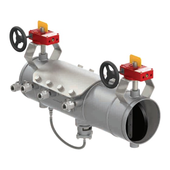
Installation, Operation and
Maintenance Manual
Deringer
™
Reduced Pressure Zone/
Reduced Pressure Detector Assemblies
Size: 40/50: 6"&8"
40X/50X: 4"&6"
WA R NI N G
!
Read this manual BEFORE using this equipment.
Failure to read and follow all safety and use information can
result in death, serious personal injury, property damage, or
damage to the equipment.
Keep this manual for future reference.
WARNING
!
You are required to consult the local building and plumbing
codes prior to installation. If the information in this manual
is not consistent with local building or plumbing codes,
the local codes should be followed. Inquire with governing
authorities for additional local requirements.
40/40X/50/50X
IOM-A-Deringer 40/40X/50/50X_6-8
Advertisement

Related Manuals for Watts AMES Deringer 40


Summary of Contents for Watts AMES Deringer 40
- Page 1 IOM-A-Deringer 40/40X/50/50X_6-8 Installation, Operation and Maintenance Manual Deringer 40/40X/50/50X ™ Reduced Pressure Zone/ Reduced Pressure Detector Assemblies Size: 40/50: 6"&8" 40X/50X: 4"&6" WA R NI N G Read this manual BEFORE using this equipment. Failure to read and follow all safety and use information can result in death, serious personal injury, property damage, or damage to the equipment.
- Page 2 " Ratchet Wrench (x2) " Ratchet Wrench Adjustable Wrench Deringer Test Cock Wrench Slip-joint Pliers Toothbrush " Socket Wood Block 2" x 4" x 5" Wood Block 1" x 2" x 16" " Socket IOM-A-Deringer 40/40X/50/50X_6-8 2005 EDP#2916006 © 2020 Watts...
- Page 3 1. 6. Using the Deringer test cock Main Test Cock Bypass Test Cock wrench or a small adjustable wrench open main test cock number 2. Closed Open Closed Open IOM-A-Deringer 40/40X/50/50X_6-8 2005 EDP#2916006 © 2020 Watts...
- Page 4 (C), gently push the second check module in the upstream direction until the second check module can easily be removed from the access port by hand. FLOW IOM-A-Deringer 40/40X/50/50X_6-8 2005 EDP#2916006 © 2020 Watts...
- Page 5 2. Remove disk retaining washer (B). 6. Reverse the order of the instructions on the previous page to 3. Use a flathead screwdriver to remove the gasket from reassemble bypass check assembly. poppet cavity (C). IOM-A-Deringer 40/40X/50/50X_6-8 2005 EDP#2916006 © 2020 Watts...
- Page 6 (F) and remove disk retainer (G). Carefully remove • Check orientation is not important when reattaching the and replace elastomer disk (D). When replacing elastomer disk check to the first check seat. IOM-A-Deringer 40/40X/50/50X_6-8 2005 EDP#2916006 © 2020 Watts...
- Page 7 Orient seat protrusions as shown the seat. In order to maintain the performance of the valve pay attention to the proper orientation of the check module. Tower Bosses Spring Arms IOM-A-Deringer 40/40X/50/50X_6-8 2005 EDP#2916006 © 2020 Watts...
- Page 8 The second check module must be fully seated to ensure retainer screws do not bind against check seat. Binding retainer screws against check seat will result in permanent damage to second check modules. Binding Not Binding FLOW IOM-A-Deringer 40/40X/50/50X_6-8 2005 EDP#2916006 © 2020 Watts...
- Page 9 (B) or seat (C) that may be preventing the piston (B) from seal- ing properly against the seat (C). This should return the relief valve to proper working order without disassembly or the use of a repair kit. IOM-A-Deringer 40/40X/50/50X_6-8 2005 EDP#2916006 © 2020 Watts...
- Page 10 IOM-A-Deringer 40/40X/50/50X_6-8 2005 EDP#2916006 © 2020 Watts...
- Page 11 2. Place the relief valve spring (C) back onto the relief valve assembly (A) and slide the valve assembly back into the relief valve body (D). Make sure the piston assembly lines up to penetrate hole (E) in top side of relief valve. IOM-A-Deringer 40/40X/50/50X_6-8 2005 EDP#2916006 © 2020 Watts...
- Page 12 5. From the OUTSIDE of the valve the dimple (C) must face directly UPSTREAM toward the #1 shutoff valve. If the dimple (C) of the pitot tube is NOT in the oriented UPSTREAM the relief valve WILL LEAK OR DUMP during flow conditions Upstream FLOW IOM-A-Deringer 40/40X/50/50X_6-8 2005 EDP#2916006 © 2020 Watts...
- Page 13 " socket wrench (G) to tighten the 4 center cover bolts (D) alternating from one side of the valve to the other. Then tighten the four corner bolts alternating from one side of the valve to the other. IOM-A-Deringer 40/40X/50/50X_6-8 2005 EDP#2916006 © 2020 Watts...
- Page 14 4. Double check to be certain of the following: • All cover bolts are tightened (E) • Deringer 50/50X: Bypass check valve cover is tightened (F) FLOW • Deringer 50/50X: Bypass meter coupling nuts are tightened (G) Open Closed Open Closed IOM-A-Deringer 40/40X/50/50X_6-8 2005 EDP#2916006 © 2020 Watts...
- Page 15 2. Slowly rotate the number 2 shutoff valve operation handle (B) counterclockwise to the open position. NOTICE Yellow/orange position indicator flags must be parallel to mainline water flow for backflow valve to be functional (C). FLOW IOM-A-Deringer 40/40X/50/50X_6-8 2005 EDP#2916006 © 2020 Watts...
- Page 16 USA: Backflow T: (978) 689-6066 • F: (978) 975-8350 • AmesFireWater.com USA: Control Valves T: (713) 943-0688 • F: (713) 944-9445 • AmesFireWater.com Canada: T: (888) 208-8927 • F: (888) 479-2887 • AmesFireWater.ca Latin America: T: (55) 4122-0138 • AmesFireWater.com IOM-A-Deringer 40/40X/50/50X_6-8 2005 EDP#2916006 © 2020 Watts...
Need help?
Do you have a question about the AMES Deringer 40 and is the answer not in the manual?
Questions and answers
i have an AMES Deringer 40 backflow preventer, i can find the serial number but where is the model number located ?