
Related Manuals for BENSHAW POWERPRO PPFP Series


Summary of Contents for BENSHAW POWERPRO PPFP Series
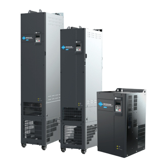
- Page 1 BENSHAW POWERPRO ™ FAN AND PUMP (PPFP) SINGLE AC DRIVES O P E N LO O P F O R VA R I A B L E TO R QU E A P P L I C AT I O N...
-
Page 2: Preface
MANUAL AVAILABILITY • This manual is delivered with the product. If you want to purchase another copy, please contact your product distributor. • Manual number: 890051-00-00. Visit the official website (http://www.benshaw.com) of BENSHAW, INC. to download the PDF version. benshaw.com... -
Page 3: Table Of Contents
Fan and Pump Single AC Drive System Composition ....18 ™ 3. Technical Specifications ......................19 3.1 Drive Ratings and Technical Specifications ..............19 3.2 Dimensions – Outline Drawings of Benshaw PowerPro ™ Fan and Pump Single AC Drive ..................24 3.2.1 Overall Dimensions of RSI-PPFP-0001-4-3-B-IP20-IM to RSI-PPFP-0250-4-3-X-IP00-IM ................ - Page 4 9.3 Replacement of Wear Parts....................108 9.3.1 Lifetime of Wear Parts ..................108 9.3.2 Number of Fans on the Drive ................109 9.3.3 Replacement of Fans ..................109 9.3.4 DC Bus Electrolytic Capacitors ................113 9.4 Storage ..........................113 9.5 Warranty .......................... 113 benshaw.com...
- Page 5 A.1.3 Selection Guidance for Braking Units ..............114 A.1.4 Appearance and Mounting Dimensions of Braking Units ........116 Fan and Pump ........117 A.2 Through-Hole Mounting of Benshaw PowerPro ™ A.3 Overall Dimensions with Optional Through-Hole Mounting Bracket ........ 119 A.4 Cable Support Bracket ....................
-
Page 6: Safety Information
3. Benshaw is not legally responsible for any personal safety accident or property losses • Do not store or transport the product caused by improper operation of this product. - Page 7 WARNING CAUTION • Be sure to use professional loading and • Product instalation, wiring, unloading equipment to move large or maintenance, inspection and heavy equipment and products. component replacement should only be performed by professionals trained • When moving the product by hand, in electrical equipment and having grip the product case tightly to avoid knowledge of electrical equipment.
- Page 8 • It is prohibited to dismantle any device or parts of the equipment and product when the power is on; otherwise, there is danger of electric shock. benshaw.com...
- Page 9 DURING SCRAPPING WARNING CAUTION • Follow the equipment maintenance and repair requirements for routine • Scrap the equipment and product and regular inspection and maintenance according to government regulations of the product and equipment, and and standards to avoid property loss maintain maintenance records.
-
Page 10: Product Information
3PH AC 380-480V 106.0A 50Hz/60Hz Rated input OUTPUT: 3PH AC 0-480V 112.0A 0-500Hz 55kW Rated output S/N: Serial Number Serial No. Benshaw AC Drive Model -INT RSI - PPFP - 0075 - 4 - 3 - B - XN01 - IM MD500 Version Mark... -
Page 11: Description Of Parts
1.2 DESCRIPTION OF PARTS The drive may have either a plastic housing or a sheet metal housing, depending on the voltage and power rating, as shown in the following figures: Fan cover Barcode (0.5~15HP) — View Cooling fan — For the serial number and model replacement, see of the drive here. - Page 12 Warning label Description CAUTION! Read the user guide for the AC drive carefully before installation or operation. DANGER! Do not remove the front cover while the power is on or within 10 minutes after the power is turned off. 10min benshaw.com...
- Page 13 Barcode — View the serial number and model Cooling fan — For of the drive here. replacement, see section 9.3. Cabling tray and fixing pin of ground cable of control Front cover— board — This ground cable For removal of can only be connected to the the front cover, ground bar after the system...
- Page 14 Warning label Description CAUTION! Read the user guide for the AC drive carefully before installation or operation. DANGER! Do not remove the front cover while the power is on or within 10 minutes after the power is turned off. 10min benshaw.com...
- Page 15 Protective cover of Top hoisting rings DC bus terminals DC bus terminals Barcode — View the serial number and model of the drive here. Nameplate Fixing pin of extension encoder card Operating panel, see section 6.1. Cabling tray and fixing pin of ground cable of control board —...
-
Page 16: System Connection
AC drive. Failure to comply will damage the drive due to static electricity. • Operating the motor at low speed reduces the cooling effect of the motor and increases motor temperature, which may result in damage to the motor. benshaw.com... -
Page 17: Benshaw Powerpro ™ Fan And Pump Single Ac Drive System Connection Diagram
Applicable motor P(+) Braking resistor Ground Figure 2-1 Benshaw PowerPro Fan and Pump Single AC Drive system composition ™ Note: The above figure shows a typical system connection diagram for the Benshaw PowerPro ™ Fan and Pump Single AC Drive. -
Page 18: Benshaw Powerpro ™ Fan And Pump Single Ac Drive System Composition
2. SYSTEM CONNECTION 2.2 BENSHAW POWERPRO FAN AND PUMP SINGLE AC DRIVE SYSTEM COMPOSITION ™ CAUTION • Do not install capacitors or surge suppressors on the output side of the AC drive. Otherwise, it may damage the AC drive. If paper is left on the drive, the drive may have abnormal heating due to poor ventilation. -
Page 19: Technical Specifications
3. TECHNICAL SPECIFICATIONS 3.1 DRIVE RATINGS, TECHNICAL SPECIFICATIONS AND DIMENSIONS Table 3-1a Model and technical data Item Specification Model Number Applicable 150% overload 7 .5 motor (HP) capacity 150% overload 7 .5 18.5 22 (kW) 110% overload 7 .5 (HP) 110% overload 7 .5 18.5 22... - Page 20 Power capacity (kVA) Thermal Heat Loss (W) 1010 1210 1570 1810 2850 2850 3560 4150 4550 5330 5060 5330 5690 6310 6910 design Air flow (CFM) 122.2 122.2 218.6 287 .2 547 638.4 722.5 882 789.4 882 benshaw.com...
- Page 21 Table 3-1b Technical Specifications of Benshaw PowerPro Fan and Pump Single AC Drive ™ Item Description Standard Input frequency Digital setting: 0.01 Hz functions resolution Analog setting: Max. frequency x 0.025% Control mode Voltage/Frequency (V/F) control Torque boost Customized boost 0.1 % to 30.0 %...
- Page 22 3. TECHNICAL SPECIFICATIONS Table 3-1b Technical Specifications of Benshaw PowerPro Fan and Pump Single AC Drive (continued) ™ Item Description Individualized PC software PC based software allows users to configure some operating parameters, functions and provides a virtual oscilloscope display that shows system status.
- Page 23 Table 3-1b Technical Specifications of Benshaw PowerPro Fan and Pump Single AC Drive (continued) ™ Item Description Protections Phase loss Input phase loss protection protection Output phase loss protection Instantaneous Trips when 250% of rated output current is exceeded. overcurrent...
-
Page 24: Dimensions - Outline Drawings Of Benshaw Powerpro Fan And Pump Single Ac Drive
3. TECHNICAL SPECIFICATIONS 3.2 DIMENSIONS – OUTLINE DRAWINGS OF BENSHAW POWERPRO ™ FAN AND PUMP SINGLE AC DRIVE 3.2.1 Overall Dimensions of RSI-PPFP-0001-4-3-B-IP20-IM to RSI-PPFP-0250-4-3-X-IP00-IM d x 4 Figure 3-2-1a Mounting Dimensions of RSI-PPFP-0001-4-3-B-IP20-IM to RSI-PPFP-0025-4-3-B-IP20-IM d x 4 Figure 3-2-1b Mounting Dimensions of RSI-PPFP-0030-4-3-B-IP20-IM to RSI-PPFP-0060-4-3-B-IP20-IM... - Page 25 Table 3-2-1 Mounting Hole Dimensions of RSI-PPFP-0001-4-3-B-IP20-IM to RSI-PPFP-0250-4-3-X-IP00-IM Hole Overall Dimensions Dimensions (mm) (mm) Hole Diameter Weight Frame Rating AC Drive Model (mm) (kg) RSI-PPFP-0001-4-3-B-IP20-IM — Ø5 RSI-PPFP-01H5-4-3-B-IP20-IM — Ø5 RSI-PPFP-0002-4-3-B-IP20-IM — Ø5 RSI-PPFP-0003-4-3-B-IP20-IM — Ø5 RSI-PPFP-0004-4-3-B-IP20-IM — Ø5 RSI-PPFP-0005-4-3-B-IP20-IM —...
-
Page 26: Overall Dimensions Of Rsi-Ppfp-0300-4-3-X-Ip00-Im To Rsi-Ppfp-0700-4-3-X-Ip00-Im
Ø13 RSI-PPFP-0400-4-3-X-IP00-IM 185 1175 1248 1284 330 Ø13 RSI-PPFP-0450-4-3-X-IP00-IM 185 1175 1248 1284 330 Ø13 RSI-PPFP-0500-4-3-X-IP00-IM 200 1280 101 1355 1405 340 Ø16 RSI-PPFP-0600-4-3-X-IP00-IM 200 1280 101 1355 1405 340 Ø16 RSI-PPFP-0700-4-3-X-IP00-IM 200 1280 101 1355 1405 340 Ø16 benshaw.com... -
Page 27: Mechanical Installation
4. MECHANICAL INSTALLATION 4.1 INSTALLATION CAUTION 4.1.1 Installation environment 1. Ambient temperature: The AC drive service 4. Ensure the mounting location is away from life is greatly influenced by the ambient direct sunlight, dampness or water drops. temperature. Do not operate the AC drive 5. -
Page 28: Mounting Clearance And Orientation
0.5 HP~20 HP A≥0.4 (10) 25 HP~30 HP A≥0.4 (10) 40 HP~50 HP A≥2.0 (50) 60 HP~200 HP A≥2.0 (50) Figure 4-1-2c Clearance for multi-drive installation (RSI-PPFP-0001-4-3-B-IP20-IM to RSI-PPFP-0250-4-3-X-IP00-IM) Notes: Roll-in drives cannot be mounted sided by side; contact the manufacturer. benshaw.com... - Page 29 Installation of an air guide plate Where an AC drive is required to be mounted directly above another AC drive, it is recommended to install an Air Guide Plate to divert exhaust cooling air from the bottom unit away from the top unit. Note: Not applicable to 250 HP to 900 HP .
-
Page 30: Installation Of Rsi-Ppfp-0001-4-3-B-Ip20-Im To Rsi-Ppfp-0250-4-3-X-Ip00-Im
AC drive, install an Air Guide Plate, as shown in Figure 4-1-2d. 1. Backplate Mounting Hoisting holes Mounting holes Figure 4-1-3a Backplate mounting of Figure 4-1-3b Backplate mounting of RSI-PPFP-0001-4-3-B-IP20-IM to RSI-PPFP-0075-4-3-B-XN01-IM to RSI-PPFP-0060-4-3-B-IP20-IM, RSI-PPFP-0250-4-3-X-IP00-IM, 0.5 HP – 50 HP 60 HP – 200 HP benshaw.com... -
Page 31: Mounting In Cabinet
Direct discharging cabinet (without fan on the top) Cabinet ventilation top cover Ventilation airflow Insulation barrier Benshaw PowerPro™ Fan and Pump Single AC Drive (600 HP) 2200 Air inlet of front door Figure 4-1-4a Direct discharging cabinet Table 4-1-4a Specification of direct discharging cabinet... - Page 32 4. MECHANICAL INSTALLATION Cabinet with fan on the top Cooling fan Ventilation airflow Insulation barrier Benshaw PowerPro™ Fan and Pump Single AC Drive (600 HP) 2200 Air inlet of front door Figure 4-1-4b Cabinet with fan on the top Table 4-1-4b Specification of cabinet with fan on the top...
-
Page 33: Dimensions Of Bottom Mounting Bracket
When choosing a cabinet, be sure to select a heavy-duty enclosure that is adequately designed to handle the weight and size (including ventilation space requirements) of the drive you’re installing in it. Install the bottom mounting bracket If your cabinet comes with mounting holes If your cabinet is not already equipped with around the base, as illustrated in the figure mounting holes around the base, drill mounting... - Page 34 525 (725) 27.5 Note: This DIN rail figure is applicable to a cabinet of 800mm wide x 600mm deep or 800mm wide x 800mm deep. 30º Detail A Figure 4-1-5c Dimensions of mounting bracket RSI-PPFP-0500-4-3-X-IP00-IM to RSI-PPFP-0700-4-3-X-IP00-IM (factory standard) benshaw.com...
-
Page 35: Assemble The Guide Rail (Model: Rsi-Ppvc-Axry-Rail-T10_T12, Optional)
4.1.6 Assemble the Guide Rail (model: RSI-PPVC-AXRY-RAIL-T10_T12, optional) As shown in Figure A, assemble the guide rail As shown in Figure C, align the two holes of the correct model. The assembled guide rail at the front of the guide rail with the studs of is shown in Figure B. -
Page 36: Installing The Ac Drive In The Cabinet
Guide rail (optional) Figure 4-1-7d Mounting the AC drive to the beam by using the four mounting holes on the back of the AC drive. Removal: When removing the drive from the enclosure, follow installation steps in reverse order. benshaw.com... - Page 37 1. Precautions Ventilation baffle Ensure the four mounting holes on the back of the drive are connected to the beams securely. After installation is completed, remove the baffle on the top of the drive. The baffle is used to prevent foreign objects such as screws from falling into the ventilation openings while the drive is being mounted in the cabinet.
-
Page 38: Electrical Wiring
Align the cover to the drive and The cover is installed. mounting position. push it down following the arrow direction until the side latches are in place. Figure 5-1a Remove and install the cover of drives RSI-PPFP-0001-4-3-B-IP20-IM to RSI-PPFP-0060-4-3-B-IP20-IM, 0.5 HP – 50 HP benshaw.com... - Page 39 2. Remove and Install the Cover of Drives RSI-PPFP-0075-4-3-B-XN01-IM to RSI-PPFP-0250-4-3-X-IP00-IM, 60 HP – 200 HP Removal Loosen the four mounting screws from the cover. Hold the cover and pull it up following the arrow direction. Installation Locate and align the mounting Secure the four mounting The cover is installed.
- Page 40 Locate and align the mounting hook at the top of Secure the six mounting screws. the cover. Align the six screws to the mounting holes on the cover. Figure 5-1c Remove and install the cover of drives RSI-PPFP-0300-4-3-X-IP00-IM to RSI-PPFP-0700-4-3-X-IP00-IM, 250 HP – 900 HP benshaw.com...
-
Page 41: Wiring
5.2.1 Standard Wiring Diagram 125 HP – 900 HP 0.5 HP – 100 HP Breaking resistor Breaking resistor Breaking unit Breaker Contactor Fuse Benshaw PowerPro ™ and Pump Drive +24V (F4-00 = 1) Forward run/stop (F4-01 = 4) Forward jog... -
Page 42: Functions Of Main Circuit Terminals And Precautions
5. ELECTRICAL WIRING 5.2.2 Functions of Main Circuit Terminals and Precautions 1. Benshaw PowerPro™ Fan and Pump Single AC Drive Main Circuit Terminals Internal brake for up to 100 HP (75kW). No internal brake for 125 HP , 150 HP and above (90kW, 110kW and above). -
Page 43: Cables, Breakers And Contactors
5.2.3 Cables, Breakers and Contactors 1. Power Input Protection 2. Power Grid System WARNING WARNING • Install protection devices (a fuse and • The drive is applicable to systems an MCCB) at power input to the drive. with neutral point grounded. If the The protection devices must provide drive is used in an IT power system protection from overcurrent and... - Page 44 5. ELECTRICAL WIRING 3. Recommended Cables, Breakers and Contactors Benshaw recommends symmetrical shielded cables as the main circuit cable, which can reduce electromagnetic radiation of the entire conductive system. If shielded cable cannot be used, the unshielded cable should be in metal conduit, grounded at both ends.
- Page 45 Table 5-2-3b Recommended Wire Sizing and Protection Devices Recommended Recommended Fuse Bussmann Pass UL Certification Contactor Breaker Rated Fuse Rated Rated Current Model Current Current Model Number Number Three-phase 380 to 480V, 50/60 Hz RSI-PPFP-0001-4-3-B-IP20-IM 3 x 0.75 0.75 3 x 0.75 10.2 FWP-5B RSI-PPFP-01H5-4-3-B-IP20-IM...
- Page 46 • Set F6-15 (braking use ratio) and F9-08 connection. (braking unit initial voltage) correctly • Fire risk! Do not connect the braking according to load after connecting the resistor directly to the DC bus. braking resistor to a drive. benshaw.com...
- Page 47 8. Drive Outputs UVW • Cable specification and installation of • Shielded cables are recommended all cables connected to the drive output for the motor. The shielding layer U, V, W must comply with local safety must be wound onto the cable regulations and relevant national (NEC, support bracket.
-
Page 48: Control Board
Table 5-2-5a Control board terminal specification Frame size Model Number Control Board Terminal Torque (in-lbs) Wire Range (AWG) T1–T8 28–12 All Models CN2,CN3 26–12 T9–T12 26–16 All Models CN2, CN3 26–16 benshaw.com... - Page 49 Table 5-2-5b Control circuit terminal function Type Terminal Name Description Power +10 V-GND +10 V power supply Provides +10 V power supply. Max. output current: 10 mA. supply Generally used to supply an external potentiometer of 1 to 5 kΩ +24 V-COM +24 V power supply Provides +24 V power supply.
-
Page 50: Panel Operation
LED display for parameters Parameter unit indicator Increment key Program key Confirm key ENTER Menu mode Shift key selection key QUICK Decrement key Run key Stop/Reset key STOP MF. K Multi-functional key Figure 6-1 Details of the operating panel benshaw.com... -
Page 51: Indicators On Led Operating Panel
6.1.1 Indicators on LED Operating Panel Table 6-1-1 Indicators on the operating panel State Indication OFF indicates the STOP status. Running Status indicators ON indicates the RUNNING status. LOCAL/REMOTE OFF indicates LOCAL panel control. Running Command LOCAL/ REMOTE indicators ON indicates REMOTE (terminal) control. LOCAL/ REMOTE FLASHING indicates under serial communication control. -
Page 52: Keys On Led Operating Panel
ENTER (Return) (Return) Level II menu LOCAL REMOT TUNE LOCAL REMOT TUNE LOCAL REMOT TUNE ENTER (Return) ENTER Level III menu Cycle LOCAL REMOT TUNE LOCAL REMOT TUNE ENTER Figure 6-1-4 Operation procedure of the three levels of menu benshaw.com... -
Page 53: Keys On Led Operating Panel
6.1.5 Keys on LED Operating Panel The following example shows how to modify F3-02 from 10.00 Hz to 15.00 Hz. LOCAL REMOT TUNE LOCAL REMOT TUNE (Return) ENTER LOCAL REMOT TUNE LOCAL REMOT TUNE LOCAL REMOT TUNE ENTER ENTER LOCAL REMOT TUNE LOCAL... -
Page 54: Drive Parameter Structure
In the figure above, in user-defined quick-view mode, the parameter is displayed as “uU3.02” . It means the function parameter F3-02 can be modified in user-modified quick-view mode and base mode in the same way. Function parameter display modes are as follows: benshaw.com... -
Page 55: View Function Parameters
1. Base mode In base mode, all function parameters of the drive are shown. You can view or edit the parameters according to section 6.1.4. Press to cycle through three function parameter display modes. In each mode, the method you use to view and modify parameter value is the same as shown in 6.1.4. - Page 56 Output current (A) Output power (kW) DI state (V) Highest eight digits DO state AI1 voltage (V) AI2 voltage (V) AI3 voltage (V) Count value Length value Load speed display PID reference Note: Values with shading are default values. benshaw.com...
- Page 57 Function Parameter Setting Code Name Default Range Description F7-04 LED display 0000 If a parameter needs to be displayed during running, set corresponding running bit to 1, and set F7-04 to hexadecimal equivalent. parameters FFFF Lowest eight digits PID feedback PLC stage Input pulse frequency (kHz) Running frequency 2 (Hz)
-
Page 58: Mf.k Key Function
Parameter display Unit’s digit: Group U The value you set for function property 0: Not displayed; parameter FP-02 determines 1: Displayed whether the operating panel Ten’s digit: Group A displays groups U and A. 0: Not displayed; 1: Displayed benshaw.com... -
Page 59: Parameters
6.2 PARAMETERS When a non-zero value is set for FP-00, the user-defined password is used. In function parameter mode and function parameter editing mode, enter the password correctly. To remove password protection, set FP-00 to 0. Password protection is not applicable to user-defined parameters. Groups F0 through FP are standard function parameters. - Page 60 ★ selection 1: Motor parameter group 2 F0-25 Acceleration/Deceleration 0: Maximum frequency (F0-10) ★ time base frequency 1: Frequency reference 2: 100 Hz F0-26 Base frequency for UP/ 0: Running frequency ★ DOWN modification 1: Frequency reference during running benshaw.com...
- Page 61 Function Code Name Setting Range Default Change Group F0: Standard Parameters (continued) F0-27 Running command + Units position: operating panel (keypad and 0000 ✩ frequency source display) + frequency reference setting channel 0: No function 1: Digital setting 2: AI1 3: AI2 4: AI3 5: Pulse reference (DI5)
- Page 62 0: Disabled 1 (Enabled) ★ 1: Enabled F3-24 Frequency gain 0 to 100 ✩ for voltage limit F3-25 Voltage gain 0 to 100 ✩ for voltage limit F3-26 Frequency rise threshold 0 to 50 Hz ★ during voltage limit benshaw.com...
- Page 63 Function Code Name Setting Range Default Change Group F4: Input Terminals F4-00 DI1 function selection 0: No function ★ 1: Forward RUN (FWD) 2: Reverse RUN (REV) Note: F4-11 must be set when F4-00 is set to 1 or 2. 3: Three-wire control 4: Forward JOG (FJOG) F4-01...
- Page 64 DI active mode selection 2 0: High level active 00000 ★ 1: Low level active Units position: DI6 active mode Tens position: DI7 active mode Hundreds position: DI8 active mode Thousand position: DI9 active mode Ten thousands position: DI10 active mode benshaw.com...
- Page 65 Function Code Name Setting Range Default Change Group F5: Output Terminals F5-00 FM terminal output 0: Pulse output (FMP) ✩ mode 1: Digital output (FMR) F5-01 FMR function selection 0: No output ✩ 1: AC Drive running 2: Fault output 3: Frequency-level detection FDT1 output 4: Frequency reached 5: Zero-speed running (no output at stop)
- Page 66 ★ motor current limit dependent F6-23 Overexcitation selection 0: Disabled ✩ 1: Enabled during deceleration 2: Enabled in the whole process F6-24 Overexcitation suppression 0% to 150% 100% ✩ current level F6-25 Overexcitation gain 1.00 to 2.50 1.25 ✩ benshaw.com...
- Page 67 Function Code Name Setting Range Default Change Group F7: Keypad Operation and Display F7-00 LED default display check 0 to 1 ✩ F7-01 MF .K key function selection 0: MF .K key disabled ★ 1: Switchover from remote control (terminal or communication) to keypad control 2: Switchover between forward rotation and reverse rotation...
- Page 68 Detection width of target 0.0% to 100.0% (maximum frequency) 0.0% ✩ frequency reached F8-22 Jump frequency function 0: Disabled ✩ 1: Enabled F8-25 Switchover frequency of 0.00 Hz to max. frequency 0.00 Hz ✩ acceleration time 1 and acceleration time 2 benshaw.com...
- Page 69 Function Code Name Setting Range Default Change Group F8: Auxiliary Functions (continued) F8-26 Switchover frequency of 0.00 Hz to max. frequency 0.00 Hz ✩ deceleration time 1 and deceleration time 2 F8-27 Set highest priority to terminal 0: Disabled ✩ JOG function 1: Enabled F8-28...
- Page 70 30: Load lost 31: PID feedback lost during running 40: Fast current limit timeout 41: Motor switchover error during running 42: Too large speed deviation 43: Motor over-speed 45: Motor overheat 51: Initial position error 55: Slave error in master-slave control benshaw.com...
- Page 71 Function Code Name Setting Range Default Change Group F9: Fault and Protection (continued) F9-17 Frequency upon 3rd — — • (latest) fault F9-18 Current upon 3rd — — • (latest) fault F9-19 Bus voltage upon 3rd — — • (latest) fault •...
- Page 72 Load lost protection 0: Disabled ✩ 1: Enabled F9-64 Load lost detection level 0.0% to 100.0% 10.0% ✩ F9-65 Load lost detection time 0.0 to 60.0s 1.0s ✩ F9-67 Overspeed detection level 0.0% to 50.0% (max. frequency) 20.0% ✩ benshaw.com...
- Page 73 Function Code Name Setting Range Default Change Group F9: Fault and Protection (continued) F9-68 Overspeed detection time 0.0s: Not detected 0.1 to 60.0s 1.0s ✩ F9-69 Detection level of speed error 0.0% to 50.0% (max. frequency) 20.0% ✩ F9-70 Detection time 0.0s: Not detected 0.1 to 60.0s 5.0s ✩...
- Page 74 Tens position: Retentive at stop 0: Not retentive at stop 1: Retentive at stop FC-18 Running time of simple PLC 0.0s (h) to 6553.5s (h) 0.0s (h) ✩ reference 0 FC-19 Acceleration/deceleration time 0 to 3 ✩ of simple PLC reference 0 benshaw.com...
- Page 75 Function Code Name Setting Range Default Change Group FC: Multi-Reference and Simple PLC Function (continued) FC-20 Running time of simple PLC reference 1 0.0s (h) to 6553.5s (h) 0.0s (h) ✩ FC-21 Acceleration/deceleration time of simple 0 to 3 ✩ PLC reference 1 FC-22 Running time of simple PLC reference 2...
- Page 76 Tens position: PROFIBUS-DP 0: PPO1 format 1: PP02 format 2: PPO3 format 3: PPO5 format FD-06 Current resolution read 0: 0.01A (≤55 kW) ✩ by communication 1: 0.1A FD-08 Profibus and CANopen 0.0 (Invalid) ✩ communication 0.1 to 60.0s timeout time benshaw.com...
- Page 77 Function Code Name Setting Range Default Change Group FE: User-Defined Parameters FE-00 User-defined parameter 0 F0-00 to FP-xx U3-17 ✩ A0-00 to Ax-xx FE-01 User-defined parameter 1 U3-18 ✩ U0-00 to U0-xx FE-02 User-defined parameter 2 F0.00 ✩ U3-00 to U3-xx FE-03 User-defined parameter 3 F0.00...
-
Page 78: Standard Parameter Table - A0 To Ac
VDO2 function selection 0: Short with physical DIx internally ✩ 1 to 41: See physical DO selection in group F5 A1-13 VDO3 function selection 0: Short with physical DIx internally ✩ 1 to 41: See physical DO selection in group F5 benshaw.com... - Page 79 Function Code Name Setting Range Default Change Group A1: Virtual DI/DO (continued) A1-14 VDO4 function selection 0: Short with physical DIx internally ✩ 1 to 41: See physical DO selection in group F5 A1-15 VDO5 function selection 0: Short with physical DIx internally ✩...
- Page 80 2: Acceleration/deceleration time selection 2 3. Acceleration/deceleration time selection 3 4: Acceleration/deceleration time selection 4 A2-64 Motor 2 torque boost 0.0%: Automatic torque boost Model ✩ 0.1 to 30.0 % dependent A2-66 Motor 2 oscillation 0 to 100 ✩ suppression gain benshaw.com...
- Page 81 Function Code Name Setting Range Default Change Group A5: Control Optimization A5-00 DPWM switchover 5.00 Hz to max. frequency 8.00 Hz ✩ frequency upper limit A5-01 PWM modulation pattern 0: Asynchronous modulation ✩ 1: Synchronous modulation A5-02 Dead zone compensation 0: Disabled ✩...
- Page 82 0: No 1: Yes Tens position: whether to send fault information to master when a fault occurs 0: No 1: Yes Hundreds position: whether to alarm when it becomes off-line 0: No 1: Yes (Err16) benshaw.com...
- Page 83 Function Code Name Setting Range Default Change Group A8: Point-point Communication (continued) A8-03 The slave received data 0: Torque reference ✩ 1: Frequency reference A8-04 Zero offset of received -100.00% to 100.00% 0.00% ★ data (torque) A8-05 Gain of received -10.00 to 100.00 1.00 ★...
-
Page 84: Monitoring Parameters
702CH U0-45 Fault information 702DH U0-59 Rated frequency 0.01% 703BH U0-60 Running frequency 0.01% 703CH U0-61 AC drive state 703DH U0-62 Current fault code 703EH U0-63 Sending torque value of point-point 0.01% 703FH communication U0-64 Number of slaves 7040H benshaw.com... - Page 85 6.2.3 Monitoring Parameters Function Communication Code Name Minimum Unit Address Group U0: Monitoring Parameters (continued) U0-66 Communication extension card type 100: CANOpen 200: PROFIBUs-DP 7042H 300: CANlink U0-67 Communication extension card version Display Range — U0-68 AC drive state on DP card Bit0: AC drive running status 7043H Bit1: Running direction...
-
Page 86: Basic Operations And Trial Run
Stop the motor, finishing commissioning. Check whether Record the modified parameters. the running status is correct according to actual load Figure 7-1 Quick commissioning steps Adjust the control effect by setting certain parameters Figure 7-2a Commissioning flowchart benshaw.com... - Page 87 Sub-procedure Set F1-00 to F1-04 according to motor nameplate Can the load be removed from the shaft of motor? Have you obtained accurate motor parameters? Set F1-06 F1-37=3: to F1-10 F1-37=2: Complete according Dynamic auto- static auto- to motor tuning tuning parameters Set V/F curve according...
-
Page 88: Checklist Before Power-On
Parameters set by the current user are backed up. Values of all the current function parameters are backed up for restoration after error caused by parameter adjustment. 501: Restore user backup parameters Restore parameters backed up by setting FP-01 to 4. benshaw.com... -
Page 89: Motor Control
7.6 MOTOR CONTROL Function Code Description Scenario F0-01: Motor F0-01 = 0: V/F Applicable to scenarios having no requirement on load or using one control mode drive to drive multiple motors, including fans and pumps. It is applicable to scenarios in which one drive is used to drive multiple motors. 7.7 START/STOP RUNNING COMMAND F0-02 Running command selection Default... - Page 90 K2 open. When K1 is closed, motor rotates in reverse direction with K2 closed. When K1 is open, motor stops regardless of matter whether K2 is Figure 7-7-2b Two-wire control mode 2 open or closed. benshaw.com...
- Page 91 F4-11 = 2: Three-wire Control Mode 1. In this mode, DI3 is a three-wire control terminal. DI1 is set for forward run function and DI2 is set for reverse run function. The parameters are set as below: Function Code Parameter Name Value Function Description F4-11...
-
Page 92: Start The Ac Drive
F6-00=1: Catching a spinning motor Max. frequency Max. frequency Initial rotation speed F0-17 Initial rotation speed=0 F0-17 Acceleration time Acceleration time Automatic rotation speed track and Automatic rotation speed detection track and detection Running command Running command Figure 7-8-1b Catching a Spinning Motor benshaw.com... -
Page 93: Start Frequency
2: Pre-excited Start This scenario is valid only for asynchronous motors and used for building magnetic field before motor operation. It can improve quick response of asynchronous motors and shorten acceleration time. The frequency curve is shown in the following figure. F0-10 F0-10 F6-00=2: Pre-excited start... -
Page 94: View Running Status
Default 0.0% Setting Range -100.0% to +100.0% F5-11 AO1 gain Default 1.00 Setting Range -10.00 to +10.00 F5-12 AO2 zero offset coefficient Default 0.00% Setting Range -100.0% to +100.0% F5-13 AO2 gain Default 1.00 Setting Range -10.00 to +10.00 benshaw.com... -
Page 95: Auto-Tuning
These four function parameters can define AO1 output (Y after correction) required AO curve. If “b” represents zero offset, “k” represents gain, “Y” represents actual output of the AO, k=F5-11 and “X” represents output frequency, then the actual output is Y=kX + b. Zero offset coefficient 100% of AO1 and AO2 b=F5-10 Parameter... - Page 96 F1-09: Mutual inductive reactance F1-10: No-load current Motor 2 A2-00 to A2-05 have the same definition. If the motor cannot be disconnected from load, set F1-37 (A2-37 in case of Motor 2) to 3 and press RUN on the operating panel. Auto-tuning begins. benshaw.com...
-
Page 97: Troubleshooting And Solutions
8. TROUBLESHOOTING AND SOLUTIONS 8.1 SAFETY INFORMATION • Tighten all screws based on the specified DANGER tightening torque. Failure to comply may • Do not disconnect the AC drive while result in fire or electric shock. power is on, and keep all breakers in •... -
Page 98: Troubleshooting During Trial Run
Increase the setting of F3-20 (overcurrent stall gain, default is 20) by 10 gradually. The heavy load is suddenly added permissible maximum setting here is 100. Decrease the setting of F3-18 (overcurrent or during acceleration stall actuating current, default is 150%) by 10% gradually. The permissible minimum setting here is 50%. benshaw.com... -
Page 99: Fault Display
Solutions in the table ENTER are for reference only. Do not repair or transform the drive QUICK by yourself. If the fault persists, contact Benshaw or our agent for technical support. STOP Stop/Reset Stop/reset MF. -
Page 100: Faults And Diagnostics
The AC drive suffers external View historical fault records. If the current value interference. is far from the overcurrent level, find interference source. If external interference does not exist, it is the drive board or hall device problem. benshaw.com... - Page 101 An external force drives motor Cancel the external force or install a braking during running. resistor. Pre-charge Bus voltage fluctuates around Contact the agent or Benshaw. resistor fault undervoltage threshold continuously. Undervoltage Instantaneous power Enable the power dip ride through function failure occurs.
- Page 102 Input phase Input phase loss occurs. Eliminate faults in external circuitry. loss Drive board, lightning protection Contact the agent or Benshaw. board, control board, or rectifier bridge is abnormal. Output phase Motor winding is damaged. Check resistance between motor wires.
- Page 103 Decrease carrier frequency or take other is too high. measures to cool the motor. Braking unit Resistance of braking resistor Replace a braking resistor of higher resistance. overload is too low. Short-circuit of Braking module is abnormal. Contact the agent or Benshaw. braking circuit...
-
Page 104: Symptoms And Diagnostics
Use a megger to measure insulation at power-on. circuited to ground. resistance of motor and motor cable. Contact the agent or Benshaw. The AC drive is damaged. The display is normal at The cooling fan is damaged or locked- Replace the cooling fan. - Page 105 Acceleration/deceleration time is improper. Set proper acceleration/deceleration time. Load fluctuates. Contact the agent or Benshaw. Err17 is detected upon The pre-charge relay or contactor Check whether the relay, contact power-on or running. is not closed.
-
Page 106: Routine Inspection And Maintenance
This is to prevent guards as specified first, and then further damage to external equipment. perform operations in accordance with instructions. • Tighten all terminal screws based on specified tightening torque. benshaw.com... -
Page 107: Routine Inspection Items
9.1.1 Routine Inspection Items Influence of ambient temperature, humidity, stopping; fluctuations in the ac power supply dust and vibration will cause aging of or load; excessive vibrations or shock loading; components in the AC drive, which may dust, metal dust, salt, sulfuric acid, chlorine cause potential faults or reduce the product atmospheres;... -
Page 108: Insulation Test On Main Circuit
9.2.2 Insulation Test on Main Circuit Before measuring insulation resistance with a megameter (a 500 VDC megameter is recommended), disconnect the main circuit from the AC drive. Do not conduct the Benshaw PowerPro ™ dielectric strength test using an insulation High Performance Single AC Drive DC 500V megameter. -
Page 109: Number Of Fans On The Drive
9.3.2 Number of Fans on the Drive Model Number Number of Fans Model Number Number of Fans Three-phase 380 to 480 V, 50/60 Hz Three-phase 380to 480 V, 50/60 Hz RSI-PPFP-0001-4-3-B-IP20-IM — RSI-PPFP-0075-4-3-B-XN01-IM RSI-PPFP-01H5-4-3-B-IP20-IM — RSI-PPFP-0100-4-3-B-XN01-IM RSI-PPFP-0002-4-3-B-IP20-IM — RSI-PPFP-0125-4-3-B-XN01-IM RSI-PPFP-0003-4-3-B-IP20-IM RSI-PPFP-0150-4-3-X-XN01-IM RSI-PPFP-0005-4-3-B-IP20-IM RSI-PPFP-0200-4-3-X-XN01-IM... - Page 110 (2) Plug the fan power cable into the socket, as shown in the figure above. Keep air flow Hook direction upward (4) Insert the two guide pins into the square holes and then press in the hook. benshaw.com...
- Page 111 Install the fan (RSI-PPFP-0003-4-3-B-IP20-IM to RSI-PPFP-0060-4-3-B-IP20-IM) cover power cable Fan power socket (1) Disconnect the fan cable (2) Remove the four screws (3) Remove the fan and fan from the drive (top view). from the drive. cover from the drive. Install the fan (RSI-PPFP-0075-4-3-B-XN01-IM to RSI-PPFP-0250-4-3-X-IP00-IM) (1) Install the fan in reverse order.
- Page 112 (2) Align the fan box to the rail and push it into the drive. (3) Connect the fan power cable connectors first before fixing the fan cover. After replacement is complete, check that the air flow direction is upright. benshaw.com...
-
Page 113: Dc Bus Electrolytic Capacitors
A reasonable repair fee will be charged for The maintenance fee is charged according damages that occur within 24 months due to Benshaw’s uniform standard. If there is to the following causes: an agreement, the agreement prevails. 1. Improper operation without following For warranty details, refer to warranty terms the instructions. -
Page 114: Appendix A Options And Accessories
(Its value varies with the system. to an external braking resistor, according The default braking voltage of the Benshaw to formula R = Vdc x Vdc / Pb. PowerPro Fan and Pump Single AC Drive is ™... - Page 115 Table A-2 Selection Guidance for Braking Units (continued) Min. 125% Braking Resistance Torque (10% D, of Braking Braking Unit Max. 10s) Resistor Model Number Model Qty. Specification Qty. Remark (Ω) RSI-PPFP-0150-4-3- RSI-PPVC-AXRY-DBRK-200 9000W 10.0Ω Input voltage ≤ 440 VAC 9.3 × 2 X-XN01-IM RSI-PPFP-0200-4-3- RSI-PPVC-AXRY-DBRK-200...
-
Page 116: Appearance And Mounting Dimensions Of Braking Units
1. Mounting Dimensions of Braking Unit (mm) RSI-PPVC-AXRY-DBRK-200 2-Ø6 Upright Cold air Figure A-2-1a Mounting dimensions Figure A-2-1b Mounting clearance of braking unit (mm) of braking unit (mm) Notes: For use and installation of braking unit, refer to the Braking Unit User Guide. benshaw.com... -
Page 117: Through-Hole Mounting Of Benshaw Powerpro ™ Fan And Pump
A.2 THROUGH-HOLE MOUNTING OF BENSHAW POWERPRO FAN AND PUMP AC DRIVE ™ 1. Through-Hole Mounting ➊ ➋ Fit the bracket to the housing and The mounting bracket is secure screws at both sides. mounted. Through-hole mounting bracket ➌ ➋ Secure the drive to the rear of the The drive is mounted. - Page 118 RSI-PPFP-0005-4-3-B-IP20-IM RSI-PPVC-AXRY- RSI-PPFP-0075-4-3-B-XN01-IM RSI-PPVC-AXRY- RSI-PPFP-07H5-4-3-B-IP20-IM FLNG-FRC RSI-PPFP-0100-4-3-B-XN01-IM FLNG-FRG RSI-PPFP-0010-4-3-B-IP20-IM RSI-PPVC-AXRY- RSI-PPFP-0125-4-3-B-XN01-IM RSI-PPVC-AXRY- RSI-PPFP-0015-4-3-B-IP20-IM FLNG-FRD RSI-PPFP-0150-4-3-X-XN01-IM FLNG-FRH RSI-PPFP-0020-4-3-B-IP20-IM RSI-PPVC-AXRY- RSI-PPFP-0200-4-3-X-XN01-IM RSI-PPVC-AXRY- FLNG-FRE RSI-PPFP-0250-4-3-X-IP00-IM RSI-PPFP-0025-4-3-B-IP20-IM FLNG-FRI Note: For details about appearence and dimensions of through-hole mounting brackets, refer to Section A.3. benshaw.com...
-
Page 119: Overall Dimensions With Optional Through-Hole Mounting Bracket
A.3 OVERALL DIMENSIONS WITH OPTIONAL THROUGH-HOLE MOUNTING BRACKET 60.5 20.5 30.5 Ø 20.5 4-M4 screw 11.5 Figure A-2-3a Dimensions of through-hole mounting bracket and hole of RSI-PPFP-0001-4-3-B-IP20-IM to RSI-PPFP-0005-4-3-B-IP20-IM... - Page 120 APPENDIX A 70.5 20.5 30.5 Ø 20.5 4-M4 screw 11.5 Figure A-2-3b Dimensions of through-hole mounting bracket and hole of RSI-PPFP-07H5-4-3-B-IP20-IM to RSI-PPFP-0010-4-3-B-IP20-IM benshaw.com...
- Page 121 73.5 Ø 4-M4 screw 31.5 Figure A-2-3c Dimensions of through-hole mounting bracket and hole of RSI-PPFP-0015-4-3-B-IP20-IM to RSI-PPFP-0020-4-3-B-IP20-IM...
- Page 122 APPENDIX A 73.5 4-M4 screw 31.5 Figure A-2-3d Dimensions of through-hole mounting bracket and hole of RSI-PPFP-0025-4-3-B-IP20-IM benshaw.com...
- Page 123 96.5 Ø 4-M5 screw Figure A-2-3e Dimensions of through-hole mounting bracket and hole of RSI-PPFP-0030-4-3-B-IP20-IM to RSI-PPFP-0040-4-3-B-IP20-IM...
- Page 124 APPENDIX A Ø 4-M6 screw 56.5 Figure A-2-3f Dimensions of through-hole mounting bracket and hole of RSI-PPFP-0050-4-3-B-IP20-IM to RSI-PPFP-0060-4-3-B-IP20-IM benshaw.com...
- Page 125 269.3 145.5 Ø 525.5 Ø 4-M8 screw Figure A-2-3g Dimensions of through-hole mounting bracket and hole of RSI-PPFP-0075-4-3-B-XN01-IM to RSI-PPFP-0100-4-3-B-XN01-IM...
- Page 126 APPENDIX A 309.2 23.5 Ø Ø 26.5 4-M8 screw 52.5 Figure A-2-3h Dimensions of through-hole mounting bracket and hole of RSI-PPFP-0125-4-3-B-XN01-IM to RSI-PPFP-0175-4-3-X-XN01-IM benshaw.com...
- Page 127 165.5 Ø Ø 13.75 427.5 4-M8 screw 145.5 Figure A-2-3i Dimensions of through-hole mounting bracket and hole of RSI-PPFP-0200-4-3-X-XN01-IM to RSI-PPFP-0250-4-3-X-IP00-IM...
-
Page 128: Cable Support Bracket
AC Drive Model RSI-PPVC-AXRY- RSI-PPFP-0001-4-3-B-IP20-IM RSI-PPVC-AXRY- RSI-PPFP-0030-4-3-B-IP20-IM RAILCBLCLM-T1 RSI-PPFP-01H5-4-3-B-IP20-IM RAILCBLCLM-T5 RSI-PPFP-0040-4-3-B-IP20-IM RSI-PPFP-0002-4-3-B-IP20-IM RSI-PPVC-AXRY- RSI-PPFP-0050-4-3-B-IP20-IM RSI-PPFP-0003-4-3-B-IP20-IM RAILCBLCLM-T6 RSI-PPFP-0060-4-3-B-IP20-IM RSI-PPFP-0005-4-3-B-IP20-IM RSI-PPVC-AXRY- RSI-PPFP-0075-4-3-B-XN01-IM RSI-PPVC-AXRY- RSI-PPFP-07H5-4-3-B-IP20-IM RAILCBLCLM-T7 RSI-PPFP-0100-4-3-B-XN01-IM RAILCBLCLM-T2 RSI-PPFP-0010-4-3-B-IP20-IM RSI-PPVC-AXRY- RSI-PPFP-0125-4-3-B-XN01-IM RSI-PPVC-AXRY- RSI-PPFP-0015-4-3-B-IP20-IM RAILCBLCLM-T8 RSI-PPFP-0150-4-3-X-XN01-IM RAILCBLCLM-T3 RSI-PPFP-0020-4-3-B-IP20-IM RSI-PPVC-AXRY- RSI-PPFP-0200-4-3-X-XN01-IM RSI-PPVC-AXRY- RSI-PPFP-0025-4-3-B-IP20-IM RAILCBLCLM-T9 RSI-PPFP-0250-4-3-X-IP00-IM RAILCBLCLM-T4 benshaw.com... -
Page 129: Ac Output Reactor
492 (150) 15 (11) 200 to 500 360 (110) Note: Contact Benshaw for assistance in sizing the correct reactor for the drive. A.6 APPLICABLE MOTOR 1. A four-pole squirrel-cage asynchronous 3. The AC drive provides standard motor induction motor is the standard motor. For parameter settings. -
Page 130: External Lcd Operating Panel
USB interface Figure A-6a Appearance of the external LCD operating panel (RSI-PPVC-AXRY-RMKP-LCD) Note: External LCD operating panel RSI-PPVC-AXRY-RMKP-LCD supports English language. 26.4 Figure A-6b Mounting dimensions Note: The mounting base (bezel) for the external LCD operating panel is RSI-PPVC-AXRY-RMKP-MNT. benshaw.com... -
Page 131: Appendix B Optional Expansion Cards, And Modbus Communication Protocol
APPENDIX B OPTIONAL EXPANSION CARDS AND MODBUS COMMUNICATION PROTOCOL The Benshaw PowerPro Fan and Pump Single AC Drive supports abundant ™ field buses and custom programming via connection with the optional expansion cards. This chapter introduces the optional card installation guideline for PG cards, function extension cards and extension communication cards. -
Page 132: Functions
Supports CANopen — Available for COMM-CNOP communication all models card RSI-PPVC-AXRY- RS-485 Supports Modbus-RTU — Available for COMM-MDBS communication all models extension card RSI-PPVC-AXRY- Profibus-DP2 Supports Profibus-DP2 — Available for COMM-PFBS communication models of 20 card HP or above benshaw.com... -
Page 133: Layout And Function Of Terminals Of Rs485 Card (Rsi-Ppvc-Axry-Comm-Mdbs)
B.2 LAYOUT AND FUNCTION OF TERMINALS OF RS485 CARD (RSI-PPVC-AXRY-COMM-MDBS) RSI-PPVC-AXRY-COMM-MDBS is specially designed to provide the drive with RS485 communication function. It adopts isolation scheme and electrical parameters conforming to international standards. It helps to implement control of drive operation and parameter setting through remote serial interface. -
Page 134: Layout And Function Of Terminals Of Extended I/O And Communications Card (Rsi-Ppvc-Axry-Iomod-Adv)
(RSI-PPVC-AXRY-IOMOD-ADV) RSI-PPVC-AXRY-IOMOD-ADV is a multifunctional I/O extension card designed for Benshaw AC drives. It has five digital input (DI) terminals, an analog input (AI) terminal, a relay output terminal, a digital output (DO) terminal and an analog output (AO) terminal. It also has the RS485 communication interface and CAN communication interface for fieldbus control. - Page 135 Table B-3b Jumper descriptions of RSI-PPVC-AXRY-IOMOD-ADV Terminal Terminal Name Function Description Terminal Arrangement AO2 output selection: Voltage: 0 V to 10 V voltage or current Current: 0 mA to 20 mA CAN terminal resistor Matching terminal resistor matching selection Not matching terminal resistor RS485 terminal resistor 1 and 2 set to ON: matching matching selection...
-
Page 136: Layout And Function Of Terminals Of Extended I/O Card-02 (Rsi-Ppvc-Axry-Iomod-Std)
If DI connected in DRAIN mode, selection OP2 connected to +24V If DI connected in SOURCE mode, OP2 connected to COM Note: Setting of jumpers shown with main terminals at the bottom of the card. Jumpers are silk-screened on the card. benshaw.com... -
Page 137: Modbus Communication Protocol
B.5 MODBUS COMMUNICATION PROTOCOL The drive provides RS485 communication interface and supports Modbus-RTU communication protocol, so that the user can implement centralized control, such as setting running commands and function codes, and reading running status and fault information of the AC drive, by using a PC or PLC. This protocol defines content and format of transmitted messages during serial communication, including master polling (or broadcasting) format and master coding method (function code for the action, transmission data, and error check). -
Page 138: Data Format
12) but the last parameter it reads must not jump to the next parameter group. Otherwise, an error occurs on response. If the slave detects a reading/writing failure caused by a communication frame error or due to other reasons, an error frame will be returned. benshaw.com... - Page 139 The frame format is described in the following table. Frame header (START) Greater than the 3.5-byte transmission idle time Slave address (ADR) Communication address: 1 to 247; 0: Broadcast address Command code (CMD) 03: Read slave parameters; 06: Write slave parameters Function code address (H) This is the internal parameter address of the AC drive, expressed in hexadecimal format.
- Page 140 0. For group A parameters, users only need to change high order A of the function code address to 4. The function code addresses are expressed as follows: High-order bytes: 00 to 0F (group F), 40 to 4F (group A) Low-order bytes: 00 to FF benshaw.com...
- Page 141 If function code F3-12 is not stored into EEPROM, the address is expressed as 030C; if function code A0-05 is not stored into EEPROM, the address is expressed as 4005; this address can only be marked as RAM. It is an invalid address when being read. Stop/RUN Parameters Parameter Parameter...
- Page 142 000F: External fault 002D: Motor overheat 0010: Communication fault 005A: Incorrect setting of PPR of the encoder 0011: Contactor fault 005B: Not connecting the encoder 0012: Current detection fault 005C: Initial position error 0013: Motor auto-tuning fault 005E: Speed feedback error benshaw.com...
-
Page 143: Rules For Parameter Address Marking
B.8 GROUP FD COMMUNICATION PARAMETER DESCRIPTION Fd-00 Baud Rate Default 5005 Setting Range Units position (Modbus) 0: 300 bps 5: 9600 bps 1: 600 bps 6: 19200 bps 2: 1200 bps 7: 38400 bps 3: 2400 bps 8: 57600 bps 4: 4800 bps 9: 115200 bps This parameter is used to set transmission speed between the host computer and AC drive. - Page 144 BENSHAW, Inc. 615 Alpha Drive Pittsburgh, PA 15238 Phone: 412.968.0100 Fax: 412.968.5415 BENSHAW Canada 550 Bright Street East Listowel, Ontario N4W 3W3 Phone: 519.291.5112 Fax: 519.291.2595 Specifications are subject to change without notice. ©2019 Benshaw Inc. 890051-00-00 Printed in the USA...
Need help?
Do you have a question about the POWERPRO PPFP Series and is the answer not in the manual?
Questions and answers