Table of Contents
Advertisement
890040-01-01
Hardware Version:
300063-01
Software Version:
810027-01-08
©
2015 Benshaw Inc.
Benshaw retains the right to change specifications and illustrations in text without prior notification.
The contents of this document may not be copied without the explicit permission of Benshaw.
RediStart
Solid State Starter
SEP
Synchronous Control
MX SEP Models
User Manual
ADVANCED CONTROLS & DRIVES
TM
Advertisement
Table of Contents
Troubleshooting

Subscribe to Our Youtube Channel
Related Manuals for BENSHAW RediStart MX 2 SEP Series


Summary of Contents for BENSHAW RediStart MX 2 SEP Series
- Page 1 Software Version: 810027-01-08 © 2015 Benshaw Inc. Benshaw retains the right to change specifications and illustrations in text without prior notification. The contents of this document may not be copied without the explicit permission of Benshaw. ADVANCED CONTROLS & DRIVES...
- Page 3 Any electrical or mechanical modifications to Benshaw products without prior written consent of Benshaw will void all warranties, and may also void UL listings or other safety certifications. Unauthorized modifications may result in product damage, operation malfunctions, or personal injury.
- Page 4 RediStart MX - SEP Synchronous Controller User Manual SAFETY PRECAUTIONS Electric Shock • This controller contains high voltage which can cause electric shock resulting in personal injury or loss of life. Prevention • Do not open the front cover while power is on or the controller is running. •...
-
Page 5: Table Of Contents
Benshaw Services ........ - Page 6 RediStart MX - SEP Synchronous Controller User Manual 3.9 Remote LCD Keypad/Display ..........34 3.9.1 Remote Display .
- Page 7 Table of Contents 7 - THEORY OF OPERATION 7.1 Control Modes of Synchronous Motor Operation ......89 7.1.1 Brush Type (Field Control) Synchronous Motor Operation .
- Page 8 RediStart MX - SEP Synchronous Controller User Manual...
-
Page 9: Introduction
1 - Introduction Introduction Using This Manual Layout This manual is divided into 9 sections. Each section contains topics related to the section. The sections are as follows: • Introduction • Technical Specifications • Installation • Keypad Operation • Parameter Groups •... -
Page 10: Benshaw Services
History Warranty Benshaw provides a 1 year standard warranty with its controllers. An extension to the 3 year warranty is provided when a Benshaw or Benshaw authorized service technician completes the installation and initial start up. The warranty data sheet must also be signed and returned. The cost of this service is not included in the price of the Benshaw controller and will be quoted specifically to each customers needs. - Page 11 1 - Introduction Contacting Information about Benshaw products and services is available by contacting Benshaw at one of the following Benshaw offices: Benshaw Corporate Headquarters Benshaw Canada 615 Alpha Drive 550 Bright Street East Pittsburgh, PA 15116 Listowel, Ontario N4W 3W3...
- Page 12 RediStart MX - SEP Synchronous Controller User Manual Interpreting Model Numbers Figure 1: RediStart MX SEP Series Model Numbers MX2SEP-125VDC-50A-3-S-C C = Open Chassis S = Solid State M = Mechanical (contactors) 1 = Single Phase Bridge 3 = Three Phase Bridge Current Rating of Bridge Voltage Rating of Field (125 or 250 VDC) MX2 Control...
-
Page 13: General Overview Of A Synchronous Field Controller
1 - Introduction General Overview of a Synchronous Field Controller General The RediStart MX SEP synchronous field controller is a microprocessor based controller for single or three- Overview phase field supply. The synch controller can be custom designed for specific applications. A few of the features are: •... - Page 14 RediStart MX - SEP Synchronous Controller User Manual...
-
Page 15: Technicalspecifications
2 - Technical Specifications Technical Specifications General Information The physical specifications of the controller vary depending upon its configuration. The applicable motor current determines the configuration and its specific application requirements. Specifications are subject to change without notice. This document covers the control electronics: •... -
Page 16: Measurements And Accuracies
RediStart MX - SEP Synchronous Controller User Manual Table 1: Terminals (Continued) Terminal Function Terminal Number Description Block Input: Ain Power Voltage or Current – Ω Voltage: 10VDC, 67K impedance Ω – Analog I/O Common Current: 20mA, 500 impedance (Hall Effect Ground (Shield) Input) Aout... -
Page 17: List Of Motor Protection Features
2 - Technical Specifications 2.2.3 List of Motor Protection Features • ANSI 27 / 59 - Adjustable over/under voltage protection (Off or 1 to 40%, time 0.1 to 90.0 sec. in 0.1 sec. intervals, independent over and under voltage levels) •... -
Page 18: Environmental Conditions
Natural convection (Fans optional) Altitude Derating Benshaw controllers are capable of operating at altitudes up to 3,300 feet (1000 meters) without requiring altitude derating. Table 6 provides the derating percentage to be considered when using a controller above 3,300 feet (1000 meters). -
Page 19: Installation
3 - Installation Installation Before You Start: 3.1.1 Inspection Before storing or installing the RediStart MX SEP Series sync controller, thoroughly inspect the device for possible shipping damage. Upon receipt: • Remove the controller from its package and inspect exterior for shipping damage. If damage is apparent, notify the shipping agent and your sales representative. -
Page 20: Safety Precautions
RediStart MX - SEP Synchronous Controller User Manual 3.1.3 Safety Precautions To ensure the safety of the individuals installing the sync controller, and the safe operation of the controller, observe the following guidelines: • Ensure that the installation site meets all required environmental conditions (refer to Site Preparation, Section 3.2.1). -
Page 21: Emc Installation Guidelines
The field supply produces 4 watts of heat per amp of current, and 26 square inches of enclosure surface is required per watt of heat generation. Contact Benshaw and ask for the enclosure sizing technical note for more information concerning controllers in sealed enclosures. Benshaw supplies controllers under 124 amps non- bypassed, with the heat sink protruding from the back of the enclosure. -
Page 22: Wiring Considerations
RediStart MX - SEP Synchronous Controller User Manual Wiring Considerations 3.4.1 Wiring Practices When making power and control signal connections, the following should be observed: • Power wiring to the motor must have the maximum possible separation from all other wiring. Do not run control wiring in the same conduit;... -
Page 23: Power And Control Drawings
3 - Installation Power and Control Drawings 3.5.1 ATL Synchronous Brushtype (Field Control) Solid State Figure 2: Sample Power Schematic for RB2 Low HP... -
Page 24: Mx 2 Atl Synchronous Brushtype With Contactors
RediStart MX - SEP Synchronous Controller User Manual 3.5.2 ATL Synchronous Brushtype with contactors Figure 3: Sample MX Power Schematic ATL Synchronous Brushtype with contactors... -
Page 25: Mx 2 Atl Synchronous Brushless
3 - Installation 3.5.3 ATL Synchronous Brushless Figure 4: Sample MX Power Schematic ATL Synchronous Brushless... -
Page 26: Mx 2 Synchronous With Power Factor Control
RediStart MX - SEP Synchronous Controller User Manual 3.5.4 Synch Controller with Power Factor Control Figure 4: Sample Power Schematic Synch Controller with Power Factor Control... -
Page 27: Power Wiring Input Line Requirements
3 - Installation Power Wiring Input Line Requirements The input line source must be an adequate source to start the motor, generally 2 times the rating of the motor FLA. (This may not apply in some cases, such as being connected to a generator). 3.6.1 Recommended Incoming Line Protection A semi-conductor fuse is needed. -
Page 28: Torque Requirements For Power Wiring Terminations
RediStart MX - SEP Synchronous Controller User Manual 3.6.5 Torque Requirements for Power Wiring Terminations Table 8: Slotted Screws and Hex Bolts Tightening torque, pound-inches (N-m) Wire size installed in conductor Slotted head NO. 10 and larger Hexagonal head-external drive socket wrench Slot width-0.047 inch Slot width-over 0.047 AWG or... -
Page 29: Control Card Layout
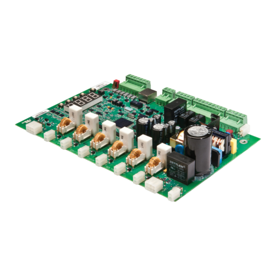
3 - Installation Control Card Layout Figure 5: Control Card Layout Jumper 120 VAC Stack In (Benshaw Only) Unfused 120 VAC Out Stack Control Control Power 120 VAC SCR 1 Auxiliary Relays: SCR 4 I/O 5-7 (P46-48) SCR 2 Digital... -
Page 30: Control Card Layout (With Communication Card For Power Factor Control)
RediStart MX - SEP Synchronous Controller User Manual Figure 6: Control Card Layout (with Communication Card for Power Factor Control) Jumper 120 VAC Stack In (Benshaw Only) Unfused 120 VAC Out Stack Control Control Power 120 VAC SCR 1 Auxiliary... -
Page 31: Control Wiring
3 - Installation Control Wiring 3.8.1 Control Power 120VAC control power is supplied to TB1. The connections are as follows: Figure 7: Control Power Wiring Example • 1 - Ground • 2 - Neutral 120VAC NEUTRAL • 3 - Neutral •... -
Page 32: Digital Input
RediStart MX - SEP Synchronous Controller User Manual 3.8.3 Digital Input TB3 is for digital inputs Start, DI1, DI2 and DI3. These digital inputs use 120VAC. These digital inputs connect as follows: • 1 - Start: Start Input • 2 - DI1: Digital Input 1 •... -
Page 33: Analog Output
3 - Installation 3.8.4 Analog Output The analog output can be configured for Voltage or Current loop. The output is shipped in the Voltage loop configuration unless specified in a custom configuration. Below, TB5 is SW1-2. When the switch is in the off position, the output is current. -
Page 34: Remote Lcd Keypad/Display
RediStart MX - SEP Synchronous Controller User Manual Remote LCD Keypad/Display The display has a NEMA 3R / IP65 service rating when properly mounted to an enclosure door with the correct gasket. The display is available in 2 versions, a small display as P/N KPMX3SLCD, and large display as P/N KPMX3LLCD. -
Page 35: Installing Display
3 - Installation 3.9.3 Installing Display The remote display is installed as follows: • Install the gasket onto the display. • Insert the display through the door cutout. • Insert the mounting clips into the holes in each side of the display. •... - Page 36 RediStart MX - SEP Synchronous Controller User Manual...
-
Page 37: Keypad Operation
4 - Keypad Operation Keypad Operation Introduction SEP provides a comprehensive set of parameters. While the controller can meet the requirements of many applications right out of the box, customization of parameter values to better suit your particular application is easily on-board, 4-digit, 7-segment LED display/keypad. -
Page 38: Changing Parameter Values
RediStart MX - SEP Synchronous Controller User Manual Changing Parameter Values Parameter change mode can be entered by: At the default meter display, press the [PARAM] key to enter parameter mode. Use the [UP] and [DOWN] keys to scroll through the available parameters. The value of the parameter can be viewed by pressing the [ENTER] key. -
Page 39: Messages Displayed
4 - Keypad Operation Messages Displayed In addition to being able to view and change parameters, various special messages may be displayed during different conditions. Here is a summary of the possible special messages. The following sections provide more detail for some of the conditions that cause special messages to be displayed. -
Page 40: Power Up
RediStart MX - SEP Synchronous Controller User Manual LCD Display Controller stopped Stopped Controller tripped on a Fault Fault Controller is locked out due to a unusual condition being present Lockout Controller is monitoring start and waiting for command and/or timer to expire before applying Wait field current. -
Page 41: Alarm Condition
4 - Keypad Operation 4.5.4 Alarm Condition When an alarm condition exists, the display alternates between displaying the selected meter and the alarm code. The alarm code is displayed as “A XX”, where XX is the alarm code. • When a no line alarm condition exists, “noL” is displayed. When the controller is stopped, the selected meter is not displayed. -
Page 42: Jump Code
RediStart MX - SEP Synchronous Controller User Manual Jump Code At the beginning of each parameter group, there is a Jump Code parameter. By changing the value of this parameter and pressing [ENTER], you can jump directly to any parameter within that group. Restoring Factory Parameter Settings To restore ALL parameters to the factory default settings, press and hold the [PARAM] and [ENTER] pushbutton switch on power up. -
Page 43: Remote Lcd Keypad And Display
4 - Keypad Operation Remote LCD Keypad and Display The MX Sync Controller can be equipped with an optional 2x16 character, back-lit LCD display/keypad that is mounted remotely from the control card. The remote keypad is NEMA 3R / IP65 when mounted directly on the door of an enclosure with the correct gasket. -
Page 44: Description Of The Keys On The Remote Lcd Keypad
RediStart MX - SEP Synchronous Controller User Manual 4.11 Description of the Keys on the Remote LCD Keypad The [UP] arrow, [DOWN] arrow, [ENTER] and [MENU] keys on the LCD keypad perform the same functions as the [UP], [DOWN], [ENTER] and [PARAM] keys on the standard keypad. Three keys have been added, with one key serving a dual function: Table 11: LCD Keypad Key Functions Function... -
Page 45: Alphanumeric Display
4 - Keypad Operation 4.12 Alphanumeric Display The remote LCD keypad and display uses a 32-character alphanumeric LCD display. All controller functions can be accessed by the keypad. The keypad allows easy access to controller programming with parameter descriptions on the LCD display. 4.12.1 Power Up Screen On power up, the software part numbers are displayed for a few seconds. -
Page 46: Parameter Group Screens
RediStart MX - SEP Synchronous Controller User Manual Table 13: Operate Screen Section B Display Description Syncing Controller is attempting to apply field and synchronize motor Motor running synchronized Synced Motor running synchronized with field forcing active Sync FF Pullout Motor pullout / pole slip detected Brushless motor control active B Ctl... -
Page 47: Meter Pages
4 - Keypad Operation 4.12.4 Meter Pages Although any meter may be viewed by changing the two meter parameters (FUN 01, FUN 02), there are 6 “Meter Pages” that are easily accessed to view all of the meter information. These meter pages are scrolled through by pressing the [UP] or [DOWN] arrows from the operate screen. -
Page 48: Fault Log Screen
RediStart MX - SEP Synchronous Controller User Manual 4.12.5 Fault Log Screen Information regarding each fault is available through the remote MX SEP LCD display. FL#: Fault ## NNNNNNNNNNNNN • FL#: = Fault Log Number. FL1 is the most recent fault and FL9 is the oldest fault. •... -
Page 49: Lockout Screens
4 - Keypad Operation 4.12.7 Lockout Screens When a lockout is present, one of the following screens will be displayed. The Main Screen is not shown until the lockout is cleared. The stack over temperature lockout will be displayed if a stack over temperature is detected. Stack Overload Lockout The control power lockout will be displayed if control power is not within specifications. -
Page 50: Procedure For Setting Data
RediStart MX - SEP Synchronous Controller User Manual 4.13 Procedure for Setting Data Select a parameter that is to be changed. To change the Current Setpoint from 10 Amps to 30 Amps: From the main screen: T Ready Ia = 0.0A Stopped Va = 480V Press [MENU] key, the display shows QST (Quick Start) screen. - Page 51 4 - Keypad Operation...
- Page 52 RediStart MX - SEP Synchronous Controller User Manual...
-
Page 53: Parameter Groups
5 - Parameter Groups Parameter Groups Introduction The MX SEP incorporates a number of parameters that allow you to configure the controller to meet the special requirements of your particular application. The parameters are organized two ways, depending on the display being used: •... -
Page 54: Led / Lcd Parameter Cross-Reference
RediStart MX - SEP Synchronous Controller User Manual LED / LCD Parameter Cross-Reference Table 15: LED / LCD Cross-Reference Parameter Control Page Parameter Control Page Group Parameter Name Group Parameter Name Number Mode Number Mode QST 01 B, BL, CF Current Setpoint I/O 01 B, BL, CF... -
Page 55: Parameter Tables
5 - Parameter Groups Parameter Tables LCD Parameters are subdivided into six groups: QST (Quick Start), CFN (Control Functions), PFN (Protection Functions), I/O (Input/Output Functions), FUN (Function), and FL1 (Fault Log). The Quick Start Group provides a collection of the parameters that are most commonly changed when commissioning a controller. -
Page 56: Protection Group
RediStart MX - SEP Synchronous Controller User Manual 5.3.3 Protection Group Table 18: Protection Group Adjust Group Display Parameter Setting Range Units Default During Page Setting Run? – — — PFN 00 Jump Code Jump to Parameter 1 – 18 PFN 01 Open Field T Open Field Trip Time... -
Page 57: I/O Group
5 - Parameter Groups 5.3.4 I/O Group Table 19: I/O Group Adjust Set- Number Display Parameter Setting Range Units Default During Page ting Run? – — — I/O 00 Jump Code Jump to Parameter 1 – 15 I/O 01 DI 1 Config DI 1 Configuration StOP : Stop... -
Page 58: Function Group
RediStart MX - SEP Synchronous Controller User Manual 5.3.5 Function Group Table 20: Function Group Adjust Number Display Parameter Setting Range Units Default During Page Setting Run? — — — FUN 00 Jump Code Jump to Parameter 1 – 16 FUN 01 Meter 1 LCD Meter 1... -
Page 59: Parameter Descriptions 6.1 Parameter Descriptions
6 - Parameter Descriptions Parameter Descriptions Parameter Descriptions The detailed parameter descriptions in this section are organized in the same order as they appear on the LCD display. Each parameter has a detailed description, displayed in the following format: MMM__ / P__ Parameter Name LCD / LED MMM: Parameter... -
Page 60: Quick Start Group
RediStart MX - SEP Synchronous Controller User Manual QST 00 Jump to Parameter LCD Display QST: Jump Code Description By changing the value of this parameter and pressing [ENTER], you can jump directly to any parameter within that group. QST 01 / P1 Current Setpoint LCD / LED QST: Cur Setpoint... - Page 61 6 - Parameter Descriptions QST 03 / P3 Inc Seq Time LCD / LED QST: Inc Seq Time Displays 30 sec Range Off, 1 200 (Default: 30) Description The Incomplete sequence timer sets how long the motor has to reach synchronization before the controller trips on an incomplete sequence fault.
- Page 62 RediStart MX - SEP Synchronous Controller User Manual Description The MX SEP can have two sources of start and stop control: Terminal and Serial. Two parameters, Local Source (QST 04 / P37), and Remote Source (QST 05 / P38), select the source of the start and stop control. If a digital input is programmed as Local / Remote, then that input selects the control source.
-
Page 63: Control Function Group
6 - Parameter Descriptions CFN 00 Jump to Parameter LCD Display CFN: Jump Code Description By changing the value of this parameter and pressing [ENTER], you can jump directly to any parameter within that group. CFN 01 / P2 Slip Percent LCD / LED CFN: Slip Percent 5 . - Page 64 RediStart MX - SEP Synchronous Controller User Manual CFN 03 / P4 Field Force Level LCD / LED CFN: F Force Lvl Displays 120% Range 50 – 125% (Default: 120) Description The Field Force Level allows a user to over drive the field at synchronization for a programmed time. This is most commonly used where the load takes more time to stabilize or the application requires a higher magnitude of torque to synchronize.
- Page 65 6 - Parameter Descriptions See Also • Dynamic Brake Level (CFN 06 / P11) on Page 65. • Dynamic Brake Time (CFN 07 / P12) on Page 65. • Dynamic Brake Delay (CFN 08 / P13) on Page CFN 06 / P11 Dynamic Brake Level LCD / LED CFN: Brake Level...
- Page 66 RediStart MX - SEP Synchronous Controller User Manual CFN 09 / P14 Inch Field Level LCD / LED CFN: Inch Field Displays 100% Range 75 – 125% (Default: 100%) Description The inching field level parameter sets the field current level that will be applied when the controller is in inching mode.
-
Page 67: Protection Group
6 - Parameter Descriptions PFN 00 Jump to Parameter LCD / LED PFN: Jump Code Displays Description By changing the value of this parameter and pressing [ENTER], you can jump directly to any parameter within that group. PFN 01 / P18 Open Field Trip Time LCD / LED PFN: Open Field T... - Page 68 RediStart MX - SEP Synchronous Controller User Manual PFN 02 / P19 Over Current Level LCD / LED PFN: Over Cur Lvl Displays 125% Range Off, 50 – 200% (Default: 125) Description The Over Current Trip Level sets the high field current trip level. This parameter should be set to the highest continuously allowable field current.
- Page 69 6 - Parameter Descriptions PFN 04 / P21 Under Current Level LCD / LED PFN: Undr Cur Lvl Displays Range Off, 5 – 100% (Default: Off) Description The Under Trip Current Level sets the low field current trip level. This parameter should be set to the lowest continuously allowable field current.
- Page 70 RediStart MX - SEP Synchronous Controller User Manual PFN 06 / P24 Over Voltage Level LCD / LED PFN: Over Vlt Lvl Displays Range Off, 1 – 40% FLA (Default: Off) Description If the controller detects a one cycle input phase voltage that is above the Over Voltage Level, the Voltage Trip Timer (PFN 08 / P26) begins counting.
- Page 71 6 - Parameter Descriptions PFN 09 / P27 Phase Loss Time LCD / LED PFN: Ph Loss Time 0 . 2 Displays 0.2 sec Range 0.1 – 5.0 seconds (Default: 0.2) Description The Phase Loss Time parameter sets the delay time on Fault 27 “Phase Loss”. This fault detects a loss of proper phase timing even when the phasing remains valid;...
- Page 72 RediStart MX - SEP Synchronous Controller User Manual PFN 12 / P30 Frequency Trip Time LCD / LED PFN: Frq Trip Tim 0 . 1 Displays 0.1 sec Range 90.0 seconds (Default: 0.1) Description The frequency delay parameter sets the time that the line frequency must go above the over frequency trip point or below the under frequency trip parameter before a high or low frequency fault will occur.
- Page 73 6 - Parameter Descriptions PFN 15 / P33 Controlled Fault Stop Enable LCD / LED PFN: Ctrl Flt En Displays Range Off – On (Default: On) Description A Controlled Fault Stop can occur if this parameter is “On”. If this parameter is on, the controller will brake the motor before faulting when the Stop Mode (CFN05 / P10) is set to “Dyn brake”.
- Page 74 RediStart MX - SEP Synchronous Controller User Manual NOTE: Selecting the Ride Through option can result in very large torque pulsations and large line current oscillations when the motor is slipping poles with the field still applied. The user should verify that the motor, mechanical, and electrical systems are capable of supporting this situation without damage.
- Page 75 6 - Parameter Descriptions I/O 00 Jump to Parameter LCD Display I/O: Jump Code Description By changing the value of this parameter and pressing [ENTER], you can jump directly to any parameter within that group. I/O 01- 03 / P40 - 42 Digital Input Configuration LCD / LED I/O: DI 1 Config...
- Page 76 RediStart MX - SEP Synchronous Controller User Manual I/O 04 / P43 Digital Input Trip Time LCD / LED I/O: Din Trp Time 0 . 1 Displays 0.1 sec Range 90.0 Seconds (Default: 0.1 Sec) Description The Digital Input Trip Time parameter sets the length of time that the digital input must be high or low before a trip occurs.
-
Page 77: I/O Group
6 - Parameter Descriptions Fld Cont Aux Controller is synchronized and the FCA Delay timer (P47 / I/O 08) has expired. Dyn Brake Used to control the dynamic braking resistor contactor. dYnb Cool Fan Ctl Heatsink fan control. Description I/O parameters 1 - 3 configure which functions are performed by the R1 to R3 relays. See Also •... - Page 78 RediStart MX - SEP Synchronous Controller User Manual I/O 10 / P55 Analog Output Span LCD / LED I/O: Aout Span Displays 100% Range 1 – 125% (Default: 100%) Description The analog output signal can be scaled using the Analog Output Span parameter. For a 0-10V output or 0- 20mA output, a 100% scaling outputs the maximum voltage (10V) or current (20mA) when the selected output function requests 100% output.
- Page 79 6 - Parameter Descriptions I/O 12 / P49 Inline Configuration LCD / LED I/O: Inline Confg 3 . 0 Displays 3.0 sec Range Off, 0 – 10.0 seconds (Default: 3.0) Description The Inline Configuration parameter controls the behavior of the No Line warning, No Line fault, and the Ready relay function.
- Page 80 RediStart MX - SEP Synchronous Controller User Manual I/O 14 / P58 Keypad Stop Disable LCD / LED I/O: Keypad Stop Displays Enabled Range Description Disabled Keypad Stop does not stop the controller Enabled Keypad Stop does stop the controller (Default) Description If “Disabled”...
-
Page 81: Function Group
6 - Parameter Descriptions FUN 00 Jump to Parameter LCD Display FUN: Jump Code Description By changing the value of this parameter and pressing [ENTER], you can jump directly to any parameter within that group. FUN 01- 02 / P17 Meter 1 - Meter 2 LCD / LED FUN: Meter 1... - Page 82 RediStart MX - SEP Synchronous Controller User Manual FUN 03 / P35 Hall Effect Ratio LCD / LED FUN: HE Ratio 2000 Displays 03 2000:1 Range 1000:1, 2000:1, 5000:1 (Default: 2000:1) Description Number of Turns Burden Resistance Hall Effect Ratio Current Low Current High (FUN04 / P36)
- Page 83 6 - Parameter Descriptions FUN 05 / P34 Input Phase Sensitivity LCD / LED FUN: Phase Order Displays Insensitive Range Description Insensitive Runs with any three phase sequence. (Default) Only runs with ABC phase sequence. Only runs with CBA phase sequence. Single Phase Single Phase.
- Page 84 RediStart MX - SEP Synchronous Controller User Manual FUN 07 / P60 Rated Power Factor LCD / LED FUN: Rated PF 1 . 0 Displays Range -0.10 – +0.10 (Default: 1.0) Description The Rated Power Factor parameter sets the reference point for the PF controller algorithm. The PF will adjust the field current to achieve this motor power factor See Also •...
- Page 85 6 - Parameter Descriptions FUN 10 / P52 Com Address (Drop #) LCD / LED FUN: Com Drop # Displays Range 1 – 247 (Default: 1) Description The Communication Address parameter sets the controller’s address for Modbus communications. See Also •...
- Page 86 The Software Part Number parameter displays the MX SEP software version, for hardware BIPC-300063-01. When calling Benshaw for service, this number should be recorded so it can be provided to the service technician. In addition to viewing the software version with this parameter, the software version is also displayed on power up.
- Page 87 6 - Parameter Descriptions FUN 15 / P59 Miscellaneous Commands LCD / LED FUN: Misc Command Displays None Range Description None No commands (Default) Powered BIST Built In Self Test with line voltage applied to the controller Reset RT Reset Run Time Meter Reflash Mode Activate Reflash Mode Store Params...
- Page 88 RediStart MX - SEP Synchronous Controller User Manual FUN 16 / P63 Passcode LCD / LED FUN: Passcode Displays Description SEP supports a 4-digit passcode. When the passcode is set, parameters may not be changed. SEP provides a means of locking parameter values so that they may not be changed. Once locked, the parameters values may be viewed on the display, but any attempt to change their values by pressing the [UP] or [DOWN] key is ignored.
-
Page 89: Theory Of Operation
• Stator IOC (Over Current) must be set for a level approximately 1.5 to 3 times the motor stator FLA that will indicate if the rotor has pulled out, and is slipping poles. Contact the motor manufacturer or Benshaw for more information. -
Page 90: Brushless Type Synchronous Motor Operation
RediStart MX - SEP Synchronous Controller User Manual Timeline Slip<Set-point Field Apply Delay Field Apply Input (CFN01 / P2) (QST02 / P3) (Digital Input) Start Sync Speed DC applied DC applied Command Reached (if no digital input) (if Field Apply Digital Input) 7.1.2 Brushless Type Synchronous Motor Operation... -
Page 91: Closed Loop Power Factor Control
7 - Theory of Operation 7.1.4 Closed Loop Power Factor Control The MX SEP controller optionally provides closed loop motor power factor (PF) control. In this mode the motor will be started as described in Sections 7.1.1 and 7.1.2 for the brush type or brushless type motor. After motor synchronization has been completed, active PF control will be enabled. -
Page 92: Hall Effect Current Sensor
RediStart MX - SEP Synchronous Controller User Manual Hall Effect Current Sensor The Hall Effect Current sensor is connected to the analog input of the MXSEP card along with a burden resistor. The analog input must be set to be a 0-10V voltage input for correct operation. The sensor scaling and burden resistance are factory selected. - Page 93 7 - Theory of Operation Figure 21: Hall Effect Connections (0 - 700 Amps) GO TO LEM + M - White Black COMMON BURDEN RESISTOR (SEE FUN03 / P 35) 300063-01-xx (MX² CARD) 300044-02-01 (SYNC CARD)
-
Page 94: Simplified I/O Schematics
RediStart MX - SEP Synchronous Controller User Manual Simplified I/O Schematics Figure 22: Digital Input Simplified Schematic Figure 23: Analog Input Simplified Schematic Figure 24: Analog Output Simplified Schematic... -
Page 95: Remote Modbus Communications
7 - Theory of Operation Remote Modbus Communications The MX SEP controller provides a Modbus RTU to support remote communication. The communication interface is RS-485, and allows up to 247 slaves to be connected to one master (with repeaters when the number of drops exceeds 31). Please refer to Figures 24 and 25 for connection diagrams. 7.4.1 Supported Commands The MX... -
Page 96: Grounding
RediStart MX - SEP Synchronous Controller User Manual 7.4.5 Grounding RS-485 buses with isolated nodes are most immune to noise when the bus is not connected to earth ground at any point. If electrical codes require that the bus be connected to earth ground, then the Common signal should be connected to earth ground at one point and one point only. -
Page 97: Dynamic Braking
7 - Theory of Operation Dynamic Braking The dynamic braking can be used to quickly stop the motor. The motor is used as a generator and the energy from the motor is dissipated into resistors. Dynamic Braking only works on Brush type motors. Braking Operation Sequence Figure 27: MX2 ATL Synchronous Brushtype with DB Braking Resistor. - Page 98 RediStart MX - SEP Synchronous Controller User Manual...
-
Page 99: Troubleshooting & Maintenance
8 - Troubleshooting & Maintenance Troubleshooting & Maintenance Safety Precautions For the safety of maintenance personal, as well as others who might be exposed to electrical hazards associated with maintenance activities, the safety related work practices of NFPA 70E, Part II, should always be followed when working on electrical equipment. -
Page 100: General Troubleshooting Charts
RediStart MX - SEP Synchronous Controller User Manual General Troubleshooting Charts The following troubleshooting charts can be used to help solve many of the common issues that may occur. 8.3.1 Motor does not start, no output to motor Condition Cause Solution Check for proper control voltage input. -
Page 101: Metering Incorrect (Hall Effect)
8 - Troubleshooting & Maintenance 8.3.4 Metering incorrect (Hall Effect) Condition Cause Solution Loose connections. Shut off all power and check all connections. Verify that the SCRs gate leads are SCR fault. connected properly and the SCRs are ok. Current or Voltage meters fluctuating with Verify that the load is actually steady and that Load actually is not steady. -
Page 102: Fault Code Table
RediStart MX - SEP Synchronous Controller User Manual Fault Code Table The following is a list of possible faults that can be generated by the MX SEP controller: Fault Code Description Detailed Description of Fault / Possible Solutions Slip percentage (CFN 01 / P2) is set too low. Incomplete Sequence Incomplete Sequence Time (QST 03 / P6) is set too low. - Page 103 8 - Troubleshooting & Maintenance Fault Code Description Detailed Description of Fault / Possible Solutions High voltage above the Over Voltage Trip Level parameter setting (PFN 06 / P24) was detected for longer than the Voltage Trip Time (PFN 08 / P26) High Line L1-L2 Verify that the actual input voltage level is correct Verify that the Rated Voltage parameter (FUN 06 / P23) is set correctly...
- Page 104 RediStart MX - SEP Synchronous Controller User Manual Fault Code Description Detailed Description of Fault / Possible Solutions The FS1, FS2 contactor did not close. Check wiring to coil of contactor. FS1 or FS2 Contactor Fault Check feedback wiring from contactor to digital input Check Cont Feedback Time (I/O13 / P48).
- Page 105 8 - Troubleshooting & Maintenance Fault Code Description Detailed Description of Fault / Possible Solutions DI#3 has been programmed as a fault type digital input and the input indicates a fault condition is present. External Fault on DIN#3 Input Verify that the appropriate Digital Input Configuration parameter has been pro- grammed correctly.
-
Page 106: Scr Testing
RediStart MX - SEP Synchronous Controller User Manual SCR Testing 8.5.1 Resistance The SCRs in the controller can be checked with a standard ohmmeter to determine their condition. Remove power from the controller before performing these checks. • Check L to F+ for each phase. The resistance should be over 50k ohms. •... -
Page 107: Built-In Self Test (Bist)
8 - Troubleshooting & Maintenance Built-In Self Test (BIST) The MX SEP has a line powered test that is used to verify the current transformer’s locations and connections and to test for shorted SCRs/power poles, open or non-firing SCRs/power poles, and ground fault conditions. 8.7.1 Powered BIST Tests The powered BIST tests are designed to be run with normal line voltage applied to the controller and a motor... -
Page 108: Bist Programming / Test Instructions
RediStart MX - SEP Synchronous Controller User Manual 8.7.2 BIST Programming / Test Instructions Step 1 LCD Display LED Display Access FUN 15 then press [ENTER]. Access P59 then press [ENTER]. Increment up to “Powered BIST” Press [UP] button to #6 then press [ENTER]. -
Page 109: Scr Replacement
8 - Troubleshooting & Maintenance SCR Replacement This section is to help with SCR replacements on stack assemblies. Please read prior to installation. 8.8.1 Typical Stack Assembly 8.8.2 SCR Removal To remove the SCR from the heatsink, loosen the two bolts (3) on the loader bar side of the clamp. Do not turn on the nuts (5). -
Page 110: Scr Clamp
RediStart MX - SEP Synchronous Controller User Manual 8.8.4 SCR Clamp SCR Clamp Parts Item # Quantity Description Loader Bar Insulator cup Bolt Washer Serrated nut (larger style clamp has 1 support bar) Indicator Washer – Quantity dependant on style of clamp 1 or 2 8.8.5 Tightening the Clamp... -
Page 111: Appendix A - Alarm Codes
Appendix A - Alarm Codes Appendix A - Alarm Codes Alarm Codes The following is a list of all MX alarm codes. The alarm codes correspond to associate fault codes. In general, an alarm indicates a condition that if continued, will result in the associated fault. Alarm Description Notes... - Page 112 RediStart MX - SEP Synchronous Controller User Manual Alarm Description Notes Code This alarm exists while the MX SEP SEP is running and a current imbal- ance above the defined threshold is detected, Current Imbalance but the delay for the fault has not yet expired. When the delay expires, a Fault 37 occurs.
-
Page 113: Appendix B - Fault Codes
Appendix B - Fault Codes Appendix B - Fault Codes Fault Codes Fault Controlled Shunt Trip Auto-Reset Description Code Fault Stop Fault Allowed No fault — — — Incomplete Sequence Loss of Synchronization Low Line Frequency High Line Frequency Input power not single phase Input power not three phase Low Line L1-L2 Low Line L2-L3... - Page 114 RediStart MX - SEP Synchronous Controller User Manual...
-
Page 115: Appendix C - Replacement Parts
Appendix C - Replacement Parts Appendix C - Replacement Parts Replacement Parts Description Part Number Size Quantity LCD Display (small) KPMX3SLCD H=63mm(2.48"), W=101mm(4") LCD Display (large) KPMX3LLCD H=77mm(3.03"), W=127mm(5") RI-100008-00 3' or 1 meter LCD display cable RI-100009-00 6' or 2 meter Remote RTD Module SPR-100P —... - Page 116 RediStart MX - SEP Synchronous Controller User Manual...
-
Page 117: Appendix D - Eu Declaration Of Conformity
MX2SEP-125VDC-100A-1-S-C MX2SEP-250VDC-100A-1-S-C MX2SEP-125VDC-200A-1-S-C MX2SEP-250VDC-200A-1-S-C MX2SEP-125VDC-400A-1-S-C MX2SEP-250VDC-400A-1-S-C MX2SEP-125VDC-600A-1-S-C MX2SEP-250VDC-600A-1-S-C Manufacturer's Benshaw, Inc. Name Manufacturer's 615 Alpha Drive Address Pittsburgh, PA 15238 United States of America The before mentioned products comply with the following EU directives and Standards: Safety UL 508 Standard for Industrial Control Equipment covering devices for starting, stopping, regulating, controlling, or protecting electric motors with ratings of 1500 volts or less. - Page 118 RediStart MX - SEP Synchronous Controller User Manual...
-
Page 119: Appendix E - Modbus Register Map
Appendix E - MODBUS Register Map Appendix E - MODBUS Register Map Modbus Register Map NOTE: All information may be accessed either through the Input registers (30000 addresses), or through the Holding registers (40000 addresses). Absolute Register Description Range Units Address Bit Mask: Bit 0:... - Page 120 RediStart MX - SEP Synchronous Controller User Manual Absolute Register Description Range Units Address no line 30031/40031 Phase Current — — 30032/40032 Line Frequency — 230 – 720, or 0 if no line 0.1 Hz -1000 to +1000 (in 16-bit two's compliment signed 30033/40033 Analog Input % —...
- Page 121 Appendix E - MODBUS Register Map Absolute Register Description Range Units Address 30122/40122 Overcurrent Trip Level 50 – 200 % RFA 30123/40123 Overcurrent Trip Delay Time 1 – 900 0.1 Sec Disable 30124/40124 Undercurrent Trip Enable — Enable 30125/40125 Undercurrent Trip Level 5 –...
- Page 122 RediStart MX - SEP Synchronous Controller User Manual Absolute Register Description Range Units Address Terminal 30144/40144 Local Control Source — Network Terminal 30145/40145 Remote Control Source — Network Field Controller Brushless Controller 30146/40146 Controller Type Current Controller — Power Factor Control Power Factor Control Brushless 30147/40147 DI 1 Function...
- Page 123 Appendix E - MODBUS Register Map Absolute Register Description Range Units Address 30162/40162 Analog Output #1 Span 1 – 125 30163/40163 Analog Output #1 Offset 0 – 99 Disabled Power 30164/40164 Auto Start Fault Power and Fault Disable 30165/40165 Keypad Stop Disable Enable No command Reset Run Time...
- Page 124 RediStart MX - SEP Synchronous Controller User Manual Absolute Register Description Range Units Address System State – 9th Most Recent Fault 30619/40619 — — Log Entry 30621/40621 Current – Most Recent Fault Log Entry — Arms Current – 2nd Most Recent Fault Log 30622/40622 —...
- Page 125 Appendix E - MODBUS Register Map Absolute Register Description Range Units Address Voltage L2 – 9th Most Recent Fault 30649/40641 — Vrms Log Entry Voltage L3 – Most Recent Fault Log 30651/40651 — Vrms Entry Voltage L3 – 2nd Most Recent Fault 30652/40652 —...
- Page 126 RediStart MX - SEP Synchronous Controller User Manual Absolute Register Description Range Units Address Software State – 9th Most Recent Fault 30679/40679 — — Log Entry Motor Slip % – Most Recent Fault Log 30681/40681 — — Entry Motor Slip % – 2nd Most Recent Fault 30682/40682 —...
- Page 127 Appendix E - MODBUS Register Map Status Register Initializing or Faulted and Braking or Bit 0 — Ready Faulted and Stopped or Lockout Otherwise Run Relay not energized Bit 1 — Running Run Relay energized Sync Relay not energized Bit 2 — Synced Sync Relay energized No alarm conditions Bit 3 —...
- Page 128 RediStart MX - SEP Synchronous Controller User Manual...
- Page 129 Publication History Revision Date ECO# 12/15/06 Initial Release 12/04/15 E4926...
- Page 130 RediStart MX - SEP Synchronous Controller User Manual BENSHAW 615 Alpha Drive Pittsburgh, PA 15238 Phone: (412) 968-0100 Fax: (412) 968-5415 ADVANCED CONTROLS & DRIVES BENSHAW Canada 550 Bright Street Listowel, Ontario N4W 3W3 Phone: (519) 291-5112 Fax: (519) 291-2595...
Need help?
Do you have a question about the RediStart MX 2 SEP Series and is the answer not in the manual?
Questions and answers