Table of Contents
Advertisement
Quick Links
Advertisement
Table of Contents

Related Manuals for Montanari MGX80


Summary of Contents for Montanari MGX80
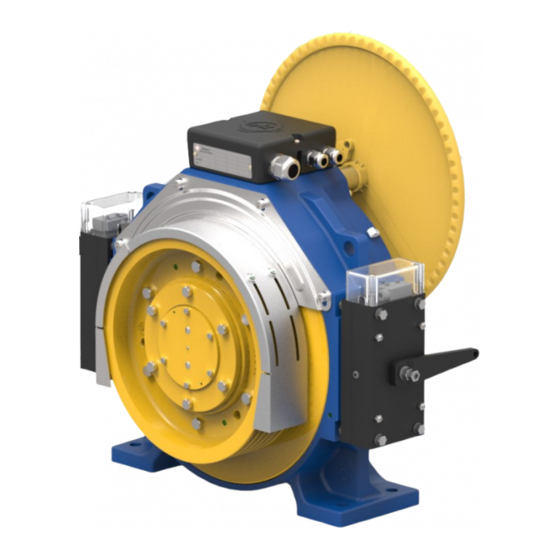
- Page 1 MANUALS INSTALLATION, USE AND MAINTENANCE GEARLESS MGX80 www.montanarigiulio.com...
- Page 2 You may check your supply, configure the inverter, download manuals, tech reports, certificates and much more. Search for Montanari Giulio App, available on Google Play and App store. SCAN THE QR TO DOWNLOAD SCAN THE QR TO DOWNLOAD...
- Page 3 We are proud to have you as a customer and user of the Montanari traction machines, and we are confident that we can work together for a long time. Thanks again for your choice.
- Page 4 REV. DATE DESCRIPTION EDITED BY VERIFIED BY APPROVED BY Technical Dept STEFANO BERTONI 09/03/2020 First Redaction Marketing Dept Alberto Mantovani (DTE) Technical Dept STEFANO BERTONI 06/04/2020 Technical data update Marketing Dept Alberto Mantovani (DTE) WARNING SYMBOLS USED IN THE MANUAL: It indicates that safety measures must be taken to avoid electric shock.
-
Page 5: Table Of Contents
ENGLISH MGX80 CONTENTS GENERAL INFORMATION ..............7 1.1 Introduction .................... 7 1.2 Copyright ....................7 SAFETY ....................8 2.1 Intended use ..................8 2.2 User’s obligations ................... 8 2.3 Correct disposal ................... 9 2.4 Specific hazards ..................9 2.5 Legal References ..................9 IDENTIFICATION AND DATA .............. - Page 6 OPERATION ..................25 8.1 Connections ..................25 8.2 Additional components ................ 25 8.3 General operation information ............. 25 TROUBLESHOOTING, MAINTENANCE AND REPAIR ......25 9.1 General information ................25 9.2 Traction/return sheave ................26 9.3 Replacement of components ............... 26 9.4 Problems, causes and solutions ............26 9.5 Maintenance and repair ...............
-
Page 7: General Information
1.2 Copyright All rights to these operating instructions belong to Montanari Giulio & C. S.r.l. The information in this manual may not be reproduced or used in an unauthori- zed manner or made available to third parties without prior approval. -
Page 8: Safety
SAFETY 2.1 Intended use The MGX80 gearless machine is supplied ready for safe and reliable use. Any modification by the user that may affect safety or reliability is prohibited; it is also prohibited to tamper with devices or functions designed to prevent acci- dental contact. -
Page 9: Correct Disposal
These plates must be kept clean and legible at all times. Missing plates must be replaced. • All spare parts can be obtained from Montanari Group. 2.3 Correct disposal Respect the environment and dispose of the product according to the regulations in force in the country of installation. -
Page 11: Dimensions
ENGLISH MGX80 3.2 Dimensions The technical drawing and the overall dimensions follow. Tab. 4 Traction Sheave [mm] Dimensions [mm] Gearless Type Ø D MGX80 Fig. 2 MGX80 www.montanarigiulio.com... -
Page 12: Transport And Storage
Montanari Giulio & C. Observe the symbols on the packaging to prevent da- mage to property or personal injury. Here are the meanings of the symbols that may appear on the packaging. -
Page 13: Storage
ENGLISH MGX80 Fig. 3 For lifting, anchor points (eyebol- ts) are provided as shown in Fig. Use only the specified eyebolts to handle the unit. 4.2 Storage The gearless machine must be stored in the position of use on a wooden base not subject to vibrations, in a covered and sheltered place. -
Page 14: Description
5.2 Main components The unit consists of the main groups as shown in Fig. 4 - 5 MGX80 is equipped with a PTC thermal probe inside the windings to protect against overheating (winding temperature up to 130°C) and with a thermo-con- tact for the activation of the fans. - Page 15 ENGLISH MGX80 MGX80 Flywheel Lifting holes Movable surface/brake Brake electromagnet Encoder Fig. 5 www.montanarigiulio.com...
-
Page 16: Brake
5.3 Brake The gearless machine is supplied with a brake that conforms to the standards indicated in paragraph 2.5. The brake system is pre-calibrated by the manufacturer and no further adjustment is required. The brake system operates as follows: • Not powered (electromagnet not powered): the brake disc is clamped by the movable surfaces (yellow arrows on Fig. -
Page 17: Installation Surface
ENGLISH MGX80 The air supply for cooling must not be prevented. 6.2 Installation surface The installation surface must be uniform and level. The levelling tolerance is 0.2 mm. The installation surface must be rigid and robust enough to withstand the forces involved. -
Page 18: Electrical Installation - Connections
The static load changes depending on the roping direction. (Fig. 9): Load direction UPWARDS STATIC LOAD: 2.500 kg LATERAL LATERAL STATIC LOAD: STATIC LOAD: 2050 kg 2050 kg DOWNWARDS STATIC LOAD: 3.000 kg Fig. 9 6.4 Electrical installation - Connections The Gearless is provided of terminal block: Clamp Phases Fig. - Page 19 ENGLISH MGX80 PTC Thermistor clamps Left Microswitch clamps Right Brake supply clamps [M1 - M2] [Lo and Li] [BR and BR] Fig. 11 Left Brake supply clamps Right Microswitch clamps [BL and BL] [Ro and Ri] • The power cable must be routed separately from the other cables.
- Page 20 Tab. 5 Condition Condition Brake disc closed Brake disc free contact contact COM. N.O. Disconnected COM. N.O. Connected Below an example for setting the parallel connection of the brake coil. Standard mode: It is possible controlling only contactor 1 and leaving contactors 2 and 3 closed. (Fig.
-
Page 21: Connection Of The Brake For Rescue System
ENGLISH MGX80 CONNECTION OF THE BRAKE FOR RESCUE SYSTEM For installations machine roomless, the cable and release lever are supplied as standard. The kit is shown in Fig. 14. Fig. 14 Connection cable for brake levers for manual rescue system (3.5 m). -
Page 22: Connection Of The Cable To The Brake Levers (Machine Roomless)
7.2 Connection of the cable to the brake levers (machine roomless) Insert the end of the cable into the lever holes. Tension and fix. Fold the end and secure with the rope clamp as shown in the figure. At the end, the result is as in the figures below. -
Page 23: Connection Of The Hand Release Lever For Machine Room Use And Rescue System Performance
ENGLISH MGX80 7.3 Connection of the hand release lever for machine room use and rescue system performance Connection and installation must be carried out in such a way that the lever and the flywheel can be operated simultaneously. Fig. 22. -
Page 24: Procedure
7.4 Procedure: • Stop the system • Calm any people inside the cab. Grasp the flywheel firmly (Fig. 22). Operate lever (Fig. 22) for manual brake release. Red arrow direction. Slowly turn the flywheel in the right direction to move the cab until the floor is reached. Close the brake by releasing the lever: green arrow direction. -
Page 25: Operation
If third party additional components or options are installed, please refer to the information in the respective separate documentation provided. 8.3 General operation information When operating the MGX80 unit, be sure to check that the following situations do not occur: • Excessive operating temperature. -
Page 26: Traction/Return Sheave
Periodically, at least once a year, check the wear of the grooves in the traction sheave. In case of slipping ropes or excessive wear, contact Montanari Giulio & C. for replacement instructions, always indicating the serial number. 9.3 Replacement of components Instructions for the replacement of any component must be requested each time from the technical department specifying the serial number. -
Page 27: Maintenance And Repair
ENGLISH MGX80 9.5 Maintenance and repair 9.5.1 General indications The unit must only be used, maintained and repaired by authorized, properly trained and qualified personnel. Compliance with the inspection and maintenance intervals is part of the condi- tions for the validity of the warranty. -
Page 28: Spare Parts
10. SPARE PARTS 10.1 General information By keeping the main spare parts and wear parts in stock, the unit can always be used. 10.2 How to order spare parts The manufacturer guarantees only genuine spare parts and accessories sup- plied by him. Other parts not supplied by the manufacturer have not been tested or appro- ved. -
Page 29: Exam Certificate Ca50.00643 Rev.2
ENGLISH MGX80 11.1 Exam certificate CA50.00643 Rev.2 www.montanarigiulio.com... -
Page 30: Compliance Declaration
MGX19 – MGV19 – MSG19M – MGS19L – MGV20M – MGV20L – MG200.3 – MGX21 – MGV25S – MGV25M – MGV25ML – MGV25L – MGV34 – MGV34S – MGV34M – MGV34ML – MGV34L – MGV34.4 – MG34S.6 – MGV34.6 – MGX75 – MGX80 – MDD035 – MDD070 – MGV30.4 – MGV30.6 – MGX53 – MGX53S. - Page 31 ENGLISH MGX80 www.montanarigiulio.com...
- Page 32 MONTANARI GROUP HEADQUARTER Montanari Giulio & C. Srl Via Bulgaria 39 - 41122 - Modena - Italia Tel: +39 059 453611 - Fax: +39 059 315890 - info@montanarigiulio.com www.montanarigiulio.com...
Need help?
Do you have a question about the MGX80 and is the answer not in the manual?
Questions and answers