
Subscribe to Our Youtube Channel
Related Manuals for Montanari RQ 200


Summary of Contents for Montanari RQ 200
- Page 1 MANUALI - GUIDES - MANUELS HANDBUCH - MANUAL INSTALLATION, USE AND MAINTENANCE SPEED GOVERNORS RQ & RQ-A 200-250-300 www.montanarigiulio.com...
- Page 2 Pag. Auf S. www.montanarigiulio.com www.montanarigiulio.com...
- Page 3 You may check your supply, configure the inverter, download manuals, tech reports, certificates and much more. Search for Montanari Giulio App, available on Google Play and App store. SCAN THE QR TO DOWNLOAD SCAN THE QR TO DOWNLOAD...
-
Page 4: Table Of Contents
CONTENTS GENERAL INFORMATION ..............43 1.1 Introduction ..................43 1.2 Copyright ..................... 43 SAFETY ....................44 2.1 Intended use ..................44 2.2 User’s obligations ................. 44 2.3 Proper disposal ..................45 2.4 Safety of operators ................45 IDENTIFICATION AND DATA .............. 46 3.1 Identification plate ................ - Page 5 SPEED GOVERNORS: RQ-A & RQ ENGLISH 7.4 Using the anti-creeping device as UCM device ........61 7.5 Emergency manoeuvre with anti-creeping device: ......64 7.6 Installation with encoder ..............65 7.7 Installation with phonic wheel ..............66 7.8 Protective cover ..................67 OPERATING TEST ................68 8.1 Static test ....................
- Page 6 Marketing Dept STEFANO BERTONI (DTE) Department The speed governor is pre-adjusted and calibrated at the factory. No intervention is allowed without authorization by Montanari Giulio & C. Srl. It indicates that safety measures must be taken to avoid electric shock.
-
Page 7: General Information
ENGLISH GENERAL INFORMATION 1.1 Introduction The speed governors by Montanari Giulio & C. are designed and tested to ensure proper operation. These operating instructions are an integral part of the speed governors and must always be kept within easy reach for consultation. -
Page 8: Safety
No liability is accepted for any malfunction due to installation not confor- ming to specifications, except in cases approved by Montanari Giulio & C. 2.2 User’s obligations The responsibility for instructions lies with the company in charge of the work. -
Page 9: Proper Disposal
These plates must be kept clean and legible at all times. Missing plates must be replaced. All spare parts can be obtained from Montanari Group. 2.3 Proper disposal Respect the environment and dispose of the product according to the regulations in force in the country of installation. -
Page 10: Identification And Data
IDENTIFICATION AND DATA 3.1 Identification plate The data shown on the plate are indicated in FIG. 1. Identification code of the body appointed for pro- duction supervision carrying out the inspection Manufacturer QR code to access all the documen- tation. Type certificate Model Certification body... -
Page 11: Technical Data
SPEED GOVERNORS: RQ-A & RQ ENGLISH 3.3 Technical data Tab. 2 RQ-A COMMON DATA MODEL MAX. TRAVEL Rated speed Rated speed ROPE Ø HEIGHT [m/s] [m/s] [mt] [mm] Version 0,15 ≤ 2,00 0,50 ≤ 1,74 6 - 6,5 0,50 ≤ 2,50 0,63 ≤... - Page 12 RQ / RQ-A Narrow base Fig. 2 RQ / RQ-A Standard base Fig. 3...
- Page 13 SPEED GOVERNORS: RQ-A & RQ ENGLISH øD øP øD øP www.montanarigiulio.com...
-
Page 14: Transport And Storage
It is recommended to verify also the condition of the goods upon receipt. In case of damages do not proceed with installation except for Montanari Giulio & C. authorization. Comply with the symbols on the packaging to prevent damage to property or personal injury. -
Page 15: Description And Operation
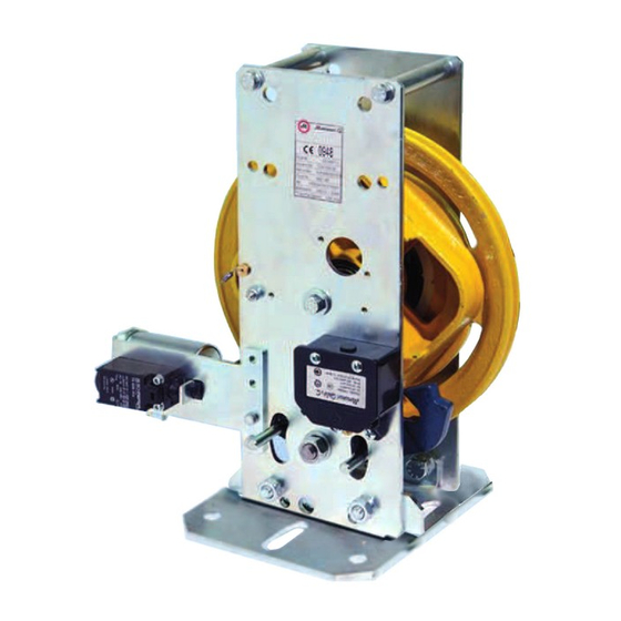
Note: A tension device is required to tension the speed governor rope ( see for example TAB163.1 and TEV on product general catalogue of Montanari Giulio & C.) 5.2 Components The following figures show the parts forming the RQ and RQ-A governor in standard version. -
Page 16: Mechanical Intervention
Arrow showing the engagement direction Spacer pins of the safety gear Test groove 7.Safety contact Fixing base Fig.6 Fig. 7 6.Pin 5.3 Mechanical intervention Fig. 5 - 6 - 7: The wheel (1) rotates on the pulley square (2) and pulls the lever (3) downwards. -
Page 17: Installation And Fixing
SPEED GOVERNORS: RQ-A & RQ ENGLISH INSTALLATION AND FIXING The speed governor must be installed in a building or in a closed travel com- partment. Do not use in an explosive atmosphere. Room temperature must range between 0°C e +40°C (unless expressly agreed/authorised). Assembly and installation must be carried out with great care by qualified and trained personnel. - Page 18 FIXING: The speed governor must be fixed checking its vertical direction with a bubble level or a lead wire. Fig. 10 Fig. 9 MAX. ALLOWED SLOPING: The speed governor must be installed so that the rope runs parallel in the pulley groove. The rope max. recommended sloping (A) is ±...
-
Page 19: Installation Of Ropes
SPEED GOVERNORS: RQ-A & RQ ENGLISH 6.2 Installation of ropes The speed governor only works in a perfect way if rope and tension device are correctly installed. 1. Gather the rope close to the governor and thread one head through the governor towards the safety gear levers. -
Page 20: Electrical Installation - Excess Speed Contact
6.3 Electrical installation - Excess speed contact FIXING: Before proceeding, cut power off Note down the following while laying the connecting cable: • single-pin cables must have a double insulation • use and laying of cables must follow the regulations in force Fig. -
Page 21: Installation Of Speed Governors With Optional Accessories
SPEED GOVERNORS: RQ-A & RQ ENGLISH INSTALLATION OF SPEED GOVERNORS WITH OPTIONAL ACCESSORIES 7.1 Electrical installation of the REMOTE CONTROL IMPORTANT: The remote control is necessary in case of governor installation in inaccessible areas as specified by the standard see paragraph 3.2 The remote control allows the governor pulley to be stopped during downwards movement for one-way versions and in both directions for two-way versions. - Page 22 Wiring diagram for remote control management. OPERATING PRINCIPLE The S1 button allows you to pull out the pin of the Remote Control Coil in the speed governor. The S2 button allows you to restore the contact with Electrical Reset once the speed governor has been activated.
- Page 23 Auxiliary Relay for managing the restoring of the Contact with Electrical Reset. REMOTE Pizzato or Montanari Contact with Electrical Reset equipped with NC / RESET NO contact in the Speed Governor. NOTE: The supply voltage of the auxiliary relays (KA2 and KA3) does not necessarily need to be the same as the supply voltage of the Contact with Electrical Reset.
-
Page 24: Electrical Installation Of The Anti-Creeping Device
7.2 Electrical installation of the ANTI-CREEPING DEVICE IMPORTANT: The anti-creeping device (Fig. 15-16) allows the governor pulley to be stopped both upwards and downwards in case of uncontrolled movements of the cab. See Tab. 4. to check the minimum distance to be run by the cab before the intervention of the safety gear after engagement, in the most unfavourable con- dition. -
Page 25: Anti-Creeping Device Specifications
SPEED GOVERNORS: RQ-A & RQ ENGLISH 7.3 Anti-creeping device specifications: This device is installed on governors and acts on the safety gear to stop the car in case of uncontrolled movements. Operation: the device is formed by an electromagnet with lever and an electric contact for controlling the piston (see Fig. - Page 26 In case of power failure in MR systems, the anti-creeping device can be opened manually or with the appropriate accessory. see: Fig. 19 - Par. 7.5 Emergency manoeuvre with anti-creeping device To avoid delays in the intervention of the anti-creeping device during normal operation of the lift (e.g.
- Page 27 SPEED GOVERNORS: RQ-A & RQ ENGLISH Example of a wiring diagram for managing the anti-creeping device. Fig. 18 Tab. 6 SYMBOL DESCRIPTION K_DOORS Door relay ANTICREEP Anti-creeping device coil + N.O. contacts - N.C K_AUX_1 Auxiliary relay with N.O. contacts - N.C. K_MOTOR Motor relay Res, Cap, Diode...
-
Page 28: Emergency Manoeuvre With Anti-Creeping Device
7.5 Emergency manoeuvre with anti-creeping device: The emergency manoeuvre can be electrical or manual. Electrical manoeuvre: feed the anti-creeping device coil at the rated voltage to free the governor and allow the movements of the car. IMPORTANT: The correct closing of the anti-creeping device contact must be checked before proceeding with any movement of the car. -
Page 29: Installation With Encoder
SPEED GOVERNORS: RQ-A & RQ ENGLISH 7.6 Installation with encoder Installation must be carried out without any electrical supply. Standard encoder: 1024 pulses per lap / Two-way + 0 Line Driver (AD26LS31) - 5 V ÷ 30 V - Cable length: 7 m For electrical connections see Tab. -
Page 30: Installation With Phonic Wheel
Tab. 8 ELECTRICAL CONNECTIONS Signals +VDC 0VDC Shield Outputs Brown A, B, 0 Blue White Black Screen (5-wire cable) EDE 9 pin Case Outputs A, /A, B, /B, 0, /0 Yellow Blue Verde Orange White Grey Black Screen (cavo 8 fili) 7.7 Installation with phonic wheel Fig. -
Page 31: Protective Cover
SPEED GOVERNORS: RQ-A & RQ ENGLISH 7.8 Protective cover Fig. 24 Fig. 23 www.montanarigiulio.com... -
Page 32: Operating Test
OPERATING TEST Perform the function test before starting. Before performing the test: • Clean the guides. • Move all persons and objects away from the lift shaft: risk of injury from crushing! • Run the entire lift travel slowly in inspection mode. 8.1 Static test •... -
Page 33: Dynamic Test
SPEED GOVERNORS: RQ-A & RQ ENGLISH 8.2 Dynamic test Check that no one is in the car or in the lift shaft. Electrical intervention: • Place the rope in the test groove (1) Fig. 26 - 27. • Allow the lift car to descend at the rated speed until the electrical contact has engaged. -
Page 34: Troubleshooting, Maintenance And Repair
Customer Service department. Montanari cannot guarantee or be held responsible for unauthorized operations on the unit, improper use, modifications made without its consent or the use of non-genuine spare parts. -
Page 35: Repairs
This prohibition also applies during repairs. It is absolutely forbidden to replace damaged or defective parts unless a written notice has been passed by the staff of Montanari Giulio & C. Srl. IMPORTANT: It is absolutely forbidden to leave the system in operation without the speed governor even for short periods. - Page 36 MONTANARI GROUP HEADQUARTER Montanari Giulio & C. Srl Via Bulgaria, 39 - 41122 - Modena - Italia Tel: +39 059 453611 - Fax: +39 059 315890 - info@montanarigiulio.com www.montanarigiulio.com...
Need help?
Do you have a question about the RQ 200 and is the answer not in the manual?
Questions and answers