Advertisement
Available languages
Available languages
Quick Links
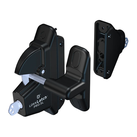
METAL–WOOD
InsTRucTIOns
Congratulations on your purchase of the Lokk•Latch PRO-SL. We are confident this
product will provide you with a lifetime of reliable gate closure. See limited Lifetime
Warranty below.
OPERATING THE LOKK•LATCH PRO-SL:
The Lokk•Latch PRO-SL automatically locks when the gate is closed and the latch fully
engages the Striker Body. To unlock from either side of the gate, simply turn the key in
the direction of the arrows until the latch unlocks (See Figure 1), then push the gate open.
You do not need to push the button on the External Access Kit (EAK) to operate this latch.
Remove the key at the 12 o'clock position. When using self-closing hinges, set the
tension on both hinges to the appropriate setting to ensure the latch fully
locks when the gate self-closes.
WARNING: Using Lokk-Latch PRO-SL on pool gates is permissible North America only.
RE-KEYING:
The Lokk•Latch PRO-SL can be re-keyed to other locks at your property. If this is desirable, DO NOT install this
product until after you have re-keyed both locks. Use only an authorized locksmith to re-key the Lokk•Latch PRO-SL.
Contact D&D Technologies for assistance if needed.
BEFORE YOU PROCEED:
• The External Access Kit (EAK) must be installed before the Latch Body.
• Install the Post Bracket to the Latch Body. See "Installing the Post Bracket" above.
• Ensure Gate Frame and Fence Post are in alignment (no offset). See dotted line X (Figure 7).
• Visible gap between Fence Post and Gate Frame must be between
• The Lokk•Latch PRO-SL for metal and wood gates can be fitted to Fence Posts ranging from 1
in depth.
NOTE: If installing the Lokk•Latch PRO-SL to a gate leading to a swimming pool or spa (see WARNING above), consult
your local building official for Code requirements in your area. The lock cylinder on the Latch Body (Figure 7) should be
used to determine legal latch height on swimming pool/spa gates.
TOOLS REQUIRED: Pencil, power drill, 3
1
/
" (89mm) # 2 Phillips-head driver bit, # 2 Phillips-head hand
2
screwdriver,
5
/
" (4mm) and
1
/
" (13mm) drill bits,
5
/
" (16mm) spade (speed) bit and a hacksaw.
32
2
8
INSTALLATION PROCEDURE:
1. Determine the proper handing (i.e. left or right-hand) of the External Access Kit (EAK). The EAK must be installed onto the
Fence Post on the opposite side of the gate as the hinges. The lock cylinder must be at the bottom of the EAK (See
Figure 1). If the factory set handing is incorrect, remove the two small screws and EAK Bracket at the rear and reverse the
Button and Bracket 180˚ (see Figure 3). The circular hole in the EAK Bracket must be positioned over the Lock Tail (Figure 2).
Re-insert the Button and EAK Bracket into the EAK Body. Re-insert the two screws using only the hand screwdriver.
2. Mark the appropriate height on the Fence Post using the pencil. This is determined by the Lock Cylinder on the Latch Body
(Figure 7). Position Fitting Jig onto Fence Post so that Hole 1 is at same height as the mark you just made with pencil. Hold
Jig firmly against corner of Fence Post so that Hole 1 is on the front of the Fence Post and the long side of the Fitting Jig is
between Fence Post and Gate Frame. Mark Hole 1 using pencil (Figure 4). Draw a line across top of the Fitting Jig.
NOTE: Hole 2 is only used on wood fence posts for mortising, which allows the side-fixing leg to be flush with post.
3. If your post is deeper than the Fitting Jig, turn the Fitting Jig 180˚ so that the line drawn across the post is aligned with the
top of Jig. Finish the line with pencil to extend across entire Fence Post.
4. Firmly position Fitting Jig against the corner using the Pencil Line as a guide. Mark Hole 1 on the opposite side so that it is
directly opposite the first marked hole (see Figure 5).
5. Drill through both sides of the Fence Post using the
1
/
" (13mm) drill bit for metal posts and the
2
(speed) bit for wood posts. Note: Be sure to drill level on wood posts so that both holes meet in the center.
6. The Push Rod should be firmly seated into EAK (Figure 2). Insert Push Rod through post and firmly place the EAK against
the corner of the post. Position EAK so that Push Rod is in center of hole and not rubbing against the edge of the hole. This
allows the Push Rod to move freely. Mark four holes for drilling using the pencil (Figure 6).
7. For metal Fence Posts, pre-drill using the
5
/
" (4mm) drill bit. Fix the EAK to the Fence Post using four 1" (25mm) self-
32
drilling screws. Do not allow the EAK to move out of position when inserting screws. Hand tighten screws with screwdriver.
8. Use the Fitting Jig to determine correct length of Push Rod: Slide Fitting Jig over Push Rod as indicated in Figure 6. Draw
a line across the Push Rod at the edge of the Jig. Cut to length using the hacksaw. NOTE: Removing the Push Rod to cut is
acceptable. Be sure to firmly re-seat Push Rod over Lock Tail when done (Figure 2).
5
/
The Push Rod should protrude by
" (16mm) from Fence Post when firmly seated into the EAK.
8
9. Turn the Push Rod so that it is at the same angle as the square hole in the back of the Latch Body (Figure 8). Slide Latch
Body over Push Rod. Position Latch Body so that the Push Rod is in the center of the hole going through the post. Do not
allow the Push Rod to rub against edge of the hole, as this may impede performance.
INSTALLING THE POST
POST BRACKET
BRACKET:
First determine the correct
handing. Lokk•Latch PRO- SL fits
both right & left-handed gates. To
determine handing, the Latch Body
must be mounted to the Fence Post
and to the same side of the gate as
the hinges. Insert the four short
screws as indicated by the drawing.
Determine the correct
handing
Figure 1
UNLOCK
1
/
" (13mm) and 1
1
/
" (38mm). 1" (25mm) is ideal.
2
2
1
/
" to 6" (38-150mm)
2
EAK
Figure 4
1
Fitting Jig
Fitting Jig
Hole 1
5
/
" (16mm) spade
8
Align
to line
Push Rod must
protrude by
(16mm) after
cutting
1
1
Cut tail flush
with Fitting Jig
10. Mark the four mounting holes on the Latch Body (2 on face, and 2 on side-fixing legs) using pencil. If mounting to a metal Fence Post, pre-drill with the
(4mm) drill bit.
11. Secure the Latch Body to Fence Post using four 1" (25mm) self-drilling screws. Be sure the Latch does not shift from position while inserting screws.
NOTE: Do not fully tighten screws using the drill. Use the hand-held screwdriver to firmly tighten so as not to strip the thread.
12. Position Striker Body onto Gate Frame. Close gate and allow Latch Body to engage Striker Bolt. Align Striker Bolt so that it's in the center of the Tongue slot (see
figure 7). Holding the Striker Body firmly against the corner of the Gate Frame, mark the center of the four slots using pencil. Be sure the screws are inserted into the
center of the slots to allow for vertical adjustment. If mounting to a metal Gate Frame, pre-drill with the
13. Secure Striker Body to Gate Frame by using the four remaining 1" (25mm) screws. Be sure the Striker Body does not shift from position while inserting screws.
NOTE: Do not fully tighten screws using the drill. Use the hand held screwdriver to firmly tighten.
14. Check latching operation to ensure smooth, reliable operation. If a vertical adjustment of the Striker Body is required, loosen the four screws using the hand-held
screwdriver. Re-align the Striker Body with the Rivet and tighten firmly by hand.
15. The Lokk•Latch PRO-SL comes with six Dress Caps to cover the screw holes. Each Dress Cap is shaped to fit its exact screw hole. Firmly slide each Dress Cap into
place. Be sure that they are properly aligned before completing insertion. Note: If you plan on re-keying both locks, do so BEFORE installation and BEFORE inserting the
Dress Caps!
Figure 7
Gate
Lock at
bottom
Frame
Figure 2
LOCK TAIL
Firmly seat
Push Rod against
Lock tail
Push Rod
Figure 3
BUTTON
EAK BRACKET
Hole 1
1
1
Draw Line
MAINTENANCE: REMOVE KEY/S FROM LOCK/S AFTER USE. Do not lubricate the latch with petroleum-based lubricants at any time - use only powdered graphite.
Figure 5
Ensure all screws are tightened firmly and that the Latch Body and/or External Access Kit are kept free of dirt, sand and other debris which could impair reliable perform-
ance. When using self-closing hinges, set the tension equally on both hinges to the appropriate setting to ensure the latch locks fully when the gate self-closes.
1
WARRANTY & LIMITATION OF LIABILITY
1
D&D Technologies' ("D&D") products are warranted to be free of defects in materials and workmanship to the original purchaser for as long as he/she owns the product.
This product will operate properly, and warranty is valid, only if installed in accordance with the instructions and specifications shown.
If a structural defect appears, the original purchaser may return the item, freight prepaid, together with proof of purchase to D&D or its approved international agents. D&D
or its agent will, at their discretion, repair or replace the defective item or part without charge to the purchaser. THIS WARRANTY SHALL NOT APPLY WHEN the product has
been tampered with, when repairs or attempted repairs have been made by unauthorized persons, where
Figure 6
EAK
the item has been subjected to misuse, abuse, accident or damage in transit, or
where the installer has not followed the instructions set out during installation,
5
/
"
8
operations, or Maintenance Requirements. IN NO EVENT SHALL THE COMPANY
BE LIABLE FOR ANY INCIDENTAL OR CONSEQUENTIAL DAMAGES. No warranty
1
is given other than that set out above. No other express or implied warranties
(including statutory warranties) apply, other than warranties which may not
Fitting Jig
be legally excluded.
EAK
Fence
(External
Post
Access Kit)
Dress Caps
Push
Rod
STRIKER
BOLT
Striker
C
Body
Post
Bracket
C
Dress
Caps
www.ddtechglobal.com
1
AUSTRALIA: Unit 6, 4-6 Aquatic Dr, Frenchs Forest NSW 2086
USA: 7731 Woodwind Drive, Huntington Beach, CA 92647
LLINSTR0030PA
5
/
"
32
5
/
" (4mm) drill bit.
32
X
Dress
Cap
Figure 8
Tongue
Slot
Latch
Body
Dress
Cap
Lock
Align Push Rod
Cylinder
to match angle
of square hole
®
•instruct_LLPRO-SL_metal/wood (21/2/07)
Advertisement

Related Manuals for D&D Technologies Lokk-Latch PRO-SL


Summary of Contents for D&D Technologies Lokk-Latch PRO-SL
- Page 1 Be sure that they are properly aligned before completing insertion. Note: If you plan on re-keying both locks, do so BEFORE installation and BEFORE inserting the locks when the gate self-closes. handing Dress Caps! WARNING: Using Lokk-Latch PRO-SL on pool gates is permissible North America only. Fence Figure 1 RE-KEYING: (External The Lokk•Latch PRO-SL can be re-keyed to other locks at your property.
- Page 2 ADVERTENCIA: El uso de Lokk-Latch PRO-SL en las puertas de las piscinas o albercas está 14. Revisar la operación del sujetador para que se desarrolle sin dificultades. Si es necesario el ajuste vertical de la caja de la cerradura hembra, aflojar los cuatro tornil- permitido únicamente en América del Norte.
Need help?
Do you have a question about the Lokk-Latch PRO-SL and is the answer not in the manual?
Questions and answers