Advertisement
Available languages
Available languages
Quick Links
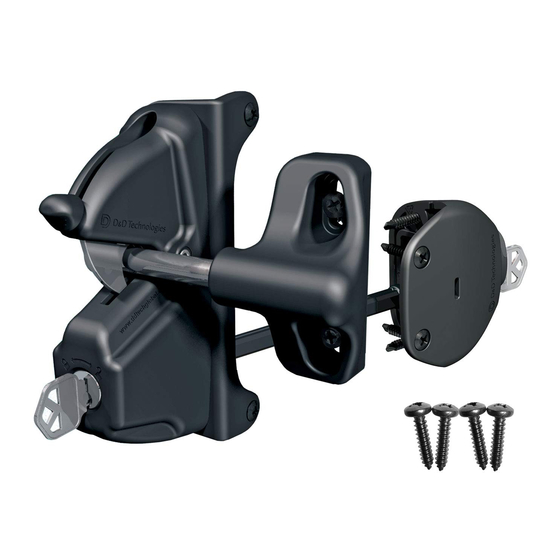
For Lokk•Latch only installation , follow Step #1
INSTALLATION PROCEDURE
• This latch is designed to be fitted to the "opening" side
of the gate. See notes at right re "handing"
• Ensure the gate frame and the latch post are in
alignment (no offset). See dotted line.
• Depending on the model you purchased, the package may contain one or
two Post Brackets. Both brackets are suitable for metal gates. The bracket with
two side legs is ideal for wood & vinyl gates, but can be used on metal gates
as well.
Gap between fence post and gate:
Latch Only:
1
3
3
Post Bracket (No side fixing legs):
"–
" (9.5–35mm)
/
/
8
8
1
3
1
Post Bracket (With side fixing legs):
"–
" (9.5–29mm)
/
/
8
8
Post sizes: 1"–6" (25–150mm)
5
Tools: Electric or cordless drill,
" [4mm] drillbit for pre-drilling
/
32
1
metal, 3
" Phillips #2 driver shaft for screws.
/
2
1. Determine the approximate height/location of
the Latch Body on the fence post. Mark the four
fixing holes. (Always predrill metal
using the
/
" [4mm] drillbit.)
5
32
2. Secure the Latch Body using four wafer-head,
self-drilling screws.
3. Locate the Striker Body on the gate frame.
Close the gate. Align the Striker Bolt in the
centre of the latch tongue (i.e. align the Bolt
with the center of rivet). Hold the Striker Body
in place and mark the four fixing holes in the
center of the fixing slots.
4. Secure the Striker Body to the gate by fixing
the remaining self-drilling screws in the center of
all four slots. (The Striker is adjustable vertically
at any time as required.)
5. Check latching operation to ensure smooth,
reliable closure. Your LOKK•LATCH is now ready
for use.
MAINTENANCE: REMOVE KEY/S FROM LOCK/S AFTER USE. Do not lubricate the latch with petroleum-based lubricants at any time - use only
powdered graphite. Ensure all screws are tightened firmly and that the Latch Body and/or Access Kit is kept free of dirt, sand and other debris which
could impair reliable performance.
WARRANTY & LIMITATION OF LIABILITY: D&D Technologies' ("D&D") products are warranted to be free of defects in materials and workman-
ship to the original purchaser for as long as he/she owns the product. This product will operate properly, and warranty is valid, only if installed in
accordance with the instructions and specifications shown. If a structural defect appears, the original purchaser may return the item, freight prepaid,
together with proof of purchase to D&D or its approved international agents. D&D or its agent will, at their discretion, repair or replace the defective
item or part without charge to the purchaser. THIS WARRANTY SHALL NOT APPLY WHEN the product has been tampered with, when repairs or attempted
repairs have been made by unauthorized persons, where the item has been subjected to misuse, abuse, accident or damage in transit, or where
the installer has not followed the instructions set out during installation, operations, or Maintenance requirements.
IN NO EVENT SHALL THE COMPANY BE LIABLE FOR ANY INCIDENTAL OR CONSEQUENTIAL DAMAGES. No warranty is
given other than that set out above. No other express or implied warranties (including statutory warranties)
apply, other than warranties which may not be legally excluded.
LLINSTR0016PA
•instr_LLS2_26/4/07
▼
STEP #1 — MAIN LATCH BODY
INSTALLING THE POST
Post Bracket
BRACKET:
Follow this procedure for installing
both Post Brackets.
If using the Post Bracket with side
legs, first determine the correct
handing. Insert the Post Bracket
into the back of the latch body
at a slight angle. Rotate the Post
Bracket in the direction of the
Determine
arrows until the plate snaps firmly
the correct
in alignment with the latch body.
handing
Then insert the single short screw.
Post Bracket
FENCE
POST
GATE
FRAME
Rivet
Rivet
STRIKER
BODY
Striker Bolt
www.ddtechglobal.com
AUSTRALIA: Unit 6, 4-6 Aquatic Dr, Frenchs Forest NSW 2086
USA: 7731 Woodwind Drive, Huntington Beach, CA 92647
For latch with External Access Kit , follow Step #1, then Step #2
STEP #2 — EXTERNAL ACCESS KIT
The External Access Kit (EAK) allows a gate to be opened and
locked from the opposite side to the latch. When installed, it is
connected to the Latch Body by an Adjustor Rod.
Gap between fence post and gate frame:
Latch + EAK:
Post Bracket (No side fixing legs):
Post Bracket (With side fixing legs):
INSTALLATION PROCEDURE
1. Measure the post depth and add 1
measurement. Wind the Adjustor Lever along the Adjustor Rod
so that the Bent End of the Adjustor Rod is this distance away from the
Adjustor Lever (see diagram 1).
2. With the latch in the unlocked position, prop the gate open. Slide the
Release Knob to the up position at the rear of the Latch Body. Take the
LATCH
adjustable Rod and, holding it vertically, slide the Adjustor Lever through
BODY
the slot in the side of the Latch Body as shown in diagram 1. Be sure the
bent end of the Adjustor Lever protrudes completely through to the other
side of the Latch Body.
3. Lower the Release Knob to the down position so that it encloses the
Adjustor Lever. Turn the key to lock the Release Knob in place. Rotate the
Adjustor Rod to the horizontal position as shown in diagram 2.
Release
Knob
4. To aid with installation, the Push Button is locked. Place the Push Button
Assembly against the opposite side of the Fence Post from the Latch Body
Tongue
and center it to the Latch Body (see diagram 3). Place the bent return of
the Adjustor Rod into the hole on the side of the Push Button as shown in
diagram 3 & 4. This will leave the Adjustor Rod at a slight angle, which is
Key
normal. Ensure the Adjustor Rod is at the correct length. Rotate the Adjus-
tor Rod, if required, for fine adjustments. The Adjustor Lever within the
Latch Body must be at the end of the slot closest to the Fence Post. Mark
the angle and position of the Adjustor Rod using a pencil (see diagram 3).
5. With the bent end of the rod firmly inside the hole on the Push Button,
slide the Fixing Shroud over the Push Button until the Fixing Shroud is
firmly against the Fence Post (see diagram 5). If the Push Button has gone
out of position, realign the Adjustor Rod to the mark you earlier made with
the pencil.
6. Secure the Fixing Shroud to the Fence Post by using the four self-drilling
screws included (Always predrill metal by using the
Unlock the Push Button and check for smooth operation. Cut off any excess
Adjustor Rod to approximately
File off any sharp edges to make smooth.
The External Access Kit is ready for use.
®
(Note: Locking the External Access Kit only locks the Push Button.
It does not lock the Latch Body, which is lockable separately).
/
" - 1
/
" (14.3 - 35mm)
9
3
16
8
/
" -1
/
" (14.3 - 29mm)
9
1
16
8
5
/
" (33mm) to that
16
Turn Key to Lock
/
" [4mm] drill bit.)
5
32
/
" (6mm) from the Adjustor Lever.
1
4
▼
Bent End
Release Knob
Adjustor Rod
Adjustor Lever
Release Knob
Adjustor Rod
Adjustor Lever
Pencil Line
Push Button
Latch
Body
Bent Return
Adjustor Lever
Fence Post
Fixing Shroud
Bent Return
Cut off any excess
Adjustor Rod
Advertisement

Related Manuals for D&D Technologies Lokk-Latch


Summary of Contents for D&D Technologies Lokk-Latch
- Page 1 For Lokk•Latch only installation , follow Step #1 For latch with External Access Kit , follow Step #1, then Step #2 ▼ ▼ STEP #1 — MAIN LATCH BODY STEP #2 — EXTERNAL ACCESS KIT INSTALLATION PROCEDURE Bent End The External Access Kit (EAK) allows a gate to be opened and •...
- Page 2 Para la instalación de Lokk•Latch únicamente , seguir el Paso No. 1 Para el cerrojo con el Juego de Acceso exterior , seguir el Paso No. 1 y luego el paso No. 2 ▼ ▼ PASO No. 1 - CAJA PRINCIPAL DEL CERROJO PASO No.
Need help?
Do you have a question about the Lokk-Latch and is the answer not in the manual?
Questions and answers