Sign In
Upload
Download
Table of Contents
Contents
Add to my manuals
Delete from my manuals
Share
URL of this page:
HTML Link:
Bookmark this page
Add
Manual will be automatically added to "My Manuals"
Print this page
×
Bookmark added
×
Added to my manuals
Manuals
Brands
Muir Manuals
Marine Equipment
STORM VR 850
Manual
Muir STORM VR 850 Manual
Vertical windlass
Hide thumbs
1
Table Of Contents
2
3
4
5
6
7
8
9
10
11
12
13
14
15
16
17
18
19
20
21
22
23
24
25
26
27
28
29
30
31
32
page
of
32
Go
/
32
Contents
Table of Contents
Troubleshooting
Bookmarks
Table of Contents
Table of Contents
Introduction
Important Information
Safe Operation
Installation
Installation Instructions
Rope Chain Management System Installation
Depth of the Chain Locker
Handy Hints
Electrical Information
Circuit Breaker
Deck Switches
Wiring Layout
Operation and Servicing
Operating Instructions
Retrieving Chain
Rope Hauling on the Capstan
Electric/Hydraulic Operation
Auto Anchor Launching
Maintenance and Assembly Instructions
Rope Chain Management System Adjustment
Troubleshooting
Warranty and Warranty Registration Card
Maintenance Schedule
Advertisement
Quick Links
1
Installation
2
Installation Instructions
3
Electrical Information
4
Operation and Servicing
5
Maintenance and Assembly Instructions
6
Troubleshooting
Download this manual
T H E
W O R L D
P O W E R
I N
A N C H O R I N G
S Y S T E M S
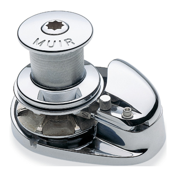
S T O R M
VR / VRC
850/900/1000/1200/1250/2200
VERTICAL WINDLASS
15th February 2016
1
www.muir.com.au
Table of
Contents
Previous
Page
Next
Page
1
2
3
4
5
Advertisement
Table of Contents
Need help?
Do you have a question about the STORM VR 850 and is the answer not in the manual?
Ask a question
Questions and answers
Related Manuals for Muir STORM VR 850
Marine Equipment Muir STORM VRC 850 Manual
Vertical windlass (32 pages)
Marine Equipment Muir STORM VRC 1250 Manual
Vertical windlass (32 pages)
Marine Equipment Muir STORM VR 600 Manual
Vertical windlass (24 pages)
Marine Equipment Muir VRC4500 Installation And Instruction Manual
Vertical windlass (9 pages)
Marine Equipment Muir VC-850 Manual
Vertical capstan (20 pages)
Marine Equipment Muir VC-800 Manual
Vertical inline capstan (16 pages)
Marine Equipment Muir EASYWEIGH VC800 Manual
Vertical inline capstan (21 pages)
Marine Equipment Muir VC500 Manual
Vertical capstans (28 pages)
This manual is also suitable for:
Storm vr 900
Storm vr 1000
Storm vr 1200
Storm vr 1250
Storm vr 2200
Storm vrc 850
...
Show all
Storm vrc 900
Storm vrc 1000
Storm vrc 1200
Storm vrc 1250
Storm vrc 2200
Table of Contents
Print
Rename the bookmark
Delete bookmark?
Delete from my manuals?
Login
Sign In
OR
Sign in with Facebook
Sign in with Google
Upload manual
Upload from disk
Upload from URL


Need help?
Do you have a question about the STORM VR 850 and is the answer not in the manual?
Questions and answers