
Subscribe to Our Youtube Channel
Related Manuals for minicopter Diabolo 700 UL


Summary of Contents for minicopter Diabolo 700 UL
- Page 1 Diabolo 700 UL # 4570 Manual minicopter Rheinstahlring 47 34246 Vellmar Germany +49 561 988 2800 info@minicopter.de www.minicopter.de...
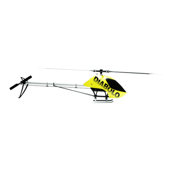
- Page 2 Introduction: Congratulations on your new Diabolo 700 UL. This model closes the hole between the smaller Diabolo 550 and the Diabolo 700/800. It is possible to fly the model with a single 6s battery pack. Best results you will get with a 10s battery pack. Then you get an agile and very precious flying model.
-
Page 3: Maintenance And Security
Maintenance and Security A radio controlled model helicopter and a speed helicopter especially is not a toy. A mistake can result in serious accidents and injuries. Please keep the following rules always in your mind: - During motor tests on the workbench, remove main and tailrotor blades and take care that nothing touches the rotating rotor heads. - Page 4 Beutel1: Main rotor shaft unit Parts overview Attach the main gearwheel hub D604 with the side, marked with a „X“ in the main gearwheel D13 and check the screw holes for corresponding together. Add six washers M3 002 to six screws M3x8 D197 and apply Loctite on the threads.
- Page 5 Put the mainrotor shaft D605 into the mainwheel hub, put a jesus bolt D77 through both and tighten the bolt well with a lock nut M4 009. If the screw does not easily fit then turn the shaft in the hub 180 degree and try again.
- Page 6 View of the assembled unit ready to mount in the frame. Note that the curved contour in the lower ball bearing block D608 must be on the left side (view in flight direction). Attach the lower ball bearing block D608 on the upper right frame D602 with two hex bolts M3x6 D196 using Loctite.
- Page 7 Bag 2: First stage shaft Parts overview Push the freewheel hub D509 from the „X“ marked side in the first stage gearwheel D611 and check mounting holes for corre- sponding. Add four washers M3 002 on four hex lense screws M3x8 D199 and attach Loctite to the therads, screw them into the holes and tighten the screws crosswise.
- Page 8 Push the mounted freewheel unit on the pinion shaft D609. Add a washer shim 10x16x0,2 033. Push the lower bearing block D612 with the flanged bearing D70 onto the shaft showing with the flanged side of the ball bearing to the freewheel unit. Note the dif- ferent inner contour of the bearing block.
- Page 9 Overview over the mounted first stage unit ready to mount in the frame. Please note that the bearing blocks are assymetric , the rounded contour is longer than the rec- tangular contour and is placed on the left side (view in flight direction). Add the toothed belt 713 in the belt wheel and position the unit as shown on the cor- responding holes of the frame.
- Page 10 Two ball bearings 3x10x4 064 are pushed on a lense screw M3x12 982, followed from a washer shim 3x6x1 051 and will be attached with Loctite on the belt tightening lever D614. A hex bolt M3x22 D332 is pushed into the longer dampening rubber ring holder D615 and mounted with Loctite on the first hole of the belt tightening lever.
- Page 11 A hex bolt M3x16 D329 ist pushed into the belt tightening lever D614 and a washer shim 3x6x0.2 455 will be added. The fixed roller is now screwed with Loc- tite into the right hole of the lower mast be- aring block (seen in flight direction).
- Page 12 Overview from the mounted unit. Bag 4: Frame completion Parts overview Before starting the mount the shown corners of the tailservo cutout should filed rectangular (radius removed). So later the tailservo mounting blocks are sitting exact- ly vertical. Filing rectangular the front corner of the tailservo cutout.
- Page 13 Break the edges of the cable slots in the gyro platform careful with a small needle file. The frame completion starts with attaching the five frame connectors D622. The four connectors, that are fixing later the left cover plate D603 must be tightened very careful with Loctite on the right frame to avoid loosing during maintenance.
- Page 14 ... and finally the lower rear connector. View of the mounted unit. The front tailboom holder clamp D620 is attached with two hex bolts M3x6 D196. Apply Loctite only on the upper screw. On the lower screw Loctite will be applied la- ter after tightening the long tailboom tigh- tening screws (long slot in the frame) and as long it will be loose.
- Page 15 Attach the rear canopy holder D618 with a lense screw M3x8 024 on the upper right frame D602 as shown. Now the gyro platform D621 will be mounted using four countersunk screws M3x6 974 and Loctite. Put the vertical frame stiffener D623 into the slot of the right frame and check for clearness, eventually file the edges a bit.
- Page 16 Now place the upper right frame D601 on the unit and check all holes for correct corresponding. Add four hex bolts M3x6 D196 on the tail- boom clamps with Loctite but still do not tighten them. Attach the upper front frame connector using two hex bolts M3x6 D196 and Loc- tite.
- Page 17 Mount the cover plate with the frame con- nectors D622 using four hex bolts M3x8 D197 using Loctite and keep them still loose. Connect the cover plate with the first stage bearings blocks D612 and D613 using four hex bolts M3x6 D196 and Loctite. Keep them still loose.
- Page 18 Check the gear mesh again and if neces- sarry follow the procedure of the assembly of bag 2. The mechanic should now stay on the ground without any tilting. If not, loose srews again and retighten them. Bag 5: Lower frame Parts overview Attach the lower left side frame D624 on the mechanics with five delrin connector...
- Page 19 For the shown point use again a hex bolt M3x8 D197 and a lock nut M3 008s ..and also this shown point will be con- nected with a hex bolt M3x8 D197 and a lock nut M3 008s. Attach the delrin con- nectors D626 after that to make the tighte- ning of the screws easy.
- Page 20 Add at the rear end (as on the left side too) a hex bolt M3x8 D197 and a lock nut M3 008s and tighten it. Add five hex bolts M3x10 D328 to the con- nectors D626 and keep them in position with the mounting wire D115.
- Page 21 Attach the right front canopy holder D619 on the same way with a lense screw M3x10 989. Attach the conroller platform D42 with four countersunk screws M3x8 025. Therefore place the holes in the connectors vertical. The mounting wire can help to find the vertical position.
- Page 22 Parts overview of the landing gear with aluminum skids (alternatively). Two landing bows D549a/b are attached on the landing bow holders D627 with four hex bolts M3x8 VA D82 using Loctite. Note that the rear landing bow is higher than the front landing bow and that the front edge is straight (the rear edge is angled on a length of about 60mm).
- Page 23 Attach two joint bolts M3x9 078 with rich Loctite on the two free arms of the swash plate D630. The swash plate guide D530 is already factory mounted with Loctite. Attach two threaded blocks D23a with two hex bolts M3x8 using Loctite at the tail- servo cut-out of the upper left side frame D601.
- Page 24 The roll servo is attached with four hex bolts M3x12 D119, washers M3 002 and lock nuts M3 008s. Therefore the open wrench #707 is a very good tool. The lo- wer right screw will be applied with Loctite and turned then in the connector D622. After gently tightenimng of the bolts the provisorically mounted single bolt on the right side can be removed.
- Page 25 Now press the cutted rubber grommet into the hole as long as it snaps.If the grommet is going thru the hole during pressing then remove it from the servo cables, put it on them on the other side and try again. Remove the upper mainshaft bearing plate and turn it as shown 90 degree.
- Page 26 Attach the elevator servo from inside into the hole of the upper right side frame D602. Put two hex bolts M3x12 D119 (Futaba- Servo) and washers M3 002 in the upper rubber grommets of the elevator servo. Position the upper manishaft bearing plate now finally and tighten it with the four M3x6 hex bolts D196 and Loctite.
- Page 27 The arms of the swashplate servos should have an effective length of about 17mm. You can use f.e. the optional servo arms D154a. Attach a hex bolt M2x10 D296, a joint ball D117 and a washer M2 001 on three servo arms. The elevator servo arm gets these parts from the not toothed side.
- Page 28 The 4mm hole in the upper left side frame is thought for (later) mounting the servo arm on the elavator servo. Rough length of the three linkages of the swashplates servos (Futaba BLS 471). Push the ball joints for the roll servo linka- ges with the number outside on the servo arms and on the joint bolts of the swash- plate.
- Page 29 Attach the elevator servo linkage as shown. Mount the servo arm hex bolt M3x8 D197 and the washer shim 3x6x1 051 using Loctite also later when the servo is under electric current and has its defined center position. Attach the swash plate holder D532 with two hex bolts M3x12 D119 using Loctite.
- Page 30 The cable of the tailservo is pushed into the left slot of the gyro plate D621. There- fore it is eventually necessary to remove the front threaded block D23a. The tailservo is attached in the tailservo slot of the upper left frame D601 with two hex bolts M3x16 D329 using Loctite.
- Page 31 Puch two O rings 591 on each spindle bush 586..and press these units in teh main rotor hub D52. We do not recommend to lubri- cat6e the O-rings. If you do it please use only a very bit of lubrication on the outside of the O-rings.
- Page 32 Add the thrust bearing 8x16x5 100. First add the non marked grooved shim with the inner diameter of 8.2mm (tilts on the spindle). Press a bit of lubrication in the groove. Add the ball cage as shown and add a bit of lubrication on the balls.
- Page 33 If the end play is correct then apply Locti- te to the threads of both hex bolts M5x12 034 and tighten them from hand first. Then tighten the screws with 8-10 Nm about (if you have a torque driver). If not then „tighten, but no too tightened“).
- Page 34 Add two lens screws M3x6 D199 using Loctite. Before tightening push both blade- grips in outside direction to eliminate play between screws and crossholes of the bladegrips. Add on the blade grip arms a hex bolt M3x8 D197 and a hex bolt M3x14 D198 and apply Loctite on the threads.
- Page 35 Attach this unit with a lense screw M3x12 982 using Loctite on the swash driver arm D65. Add on the other end of the swash driver arm a lense screw M3x10 989 and on the inner side a washer shim 3x6x0,2 455 and attach on the screw thread Loctite.
- Page 36 Push the jesus bolt D78 thru the corres- ponding holes of mainrotorhub and main- rotor shaft and tighten it with a lock nut M4 009. If the bolt cannot be easily mounted then turn the head 180 degree on the shaft and try again.
- Page 37 For turning the ball joint you can use a 3mm Ø hex wrench. But the first turnes should be made from hand. Another way is to screw the ball links on with a accu screw driver. This is depen- dedn from type and works not always. Important is less play in the grips but also no tightening, so that the ball joint can be turned without risk of slipping.
- Page 38 Attach the double ball joint linkage with a lense screw M3x12 989 and enough Loctite on the swashplate. Mount the rotorblades screws 90a with spacer shims 1050 and nut M5 010 provi- sorically. Bag 8: Motor mount Parts overview [Note: The motor is shown as sample and available as equipment] Attach the motor with for lense screws M4x8 D106 using Loctite on the motor-...
- Page 39 Push the motor pinion D37 (18-22 teeth) on the shaft so that one threaded hole is corresponding with the flat spot on the mo- tor shaft. Check for a clearance between pinion and motorplate of 0.5-1mm. Then tighten the pinion on the flat spot with a grub screw M4x5 035 using Loctite.
- Page 40 View of the motor area. Built in is a X- Nova 4025-670 for 10s use. Alternatively motor with diameters upto 55.5mm can be used. Note: A 4025 motor (or a 4030) is for the most applications of use absolutely enough. View of the mounted mechanic Bag 9: Tailboom Parts overview...
- Page 41 Then add in the front end also some drops of JB weld into the tailboom just before the front end of the cardboard. Now push the cardboard into the boom that the rear end of the cardboard is about 5mm (1/5“) before the slots are beginning. Press the cardboard carefully on the tailb- boom surface and remove resin rests in the rear and the front end of the tailboom...
- Page 42 ... and turn it 90 degree to the right. The tail gear housing D246 is attached with the rudder fin holder D44 and the two bracket mounts D43a with two hex bolts M3x10 D328 using Loctite. Check that the bolts are still as loose as possible to fit easily with the tailboom.
- Page 43 Push the tailrotor shaft D245 from the right side into the tailrotor housing as far that the distance washer D646 can be placed on the shaft end with the flanged side to the ball bearing. Push now the belt wheel into the tailrotor housing.
- Page 44 Bend the staple in that way that it can be used for pulling the rubber ring D66 thru the bush D60. Place the two ends of the rubber ring into the staple..and pull them with a pliers thru the bush.
- Page 45 Attach the rudder fin D640 on the rudder fin holder D44 with two hex bolts M3x8 D197 using Loctite. Bag 10: Tailrotor Parts overview Push a conic spacer bush D256 on the tailrotor hub D255 (cone inside). Now add a ball bearing 5x10x4 942, the blade grip holder ring 980, a washer shim 7x10x0,2 054...
- Page 46 ...and another ball bearing 5x10x4 942 fol- lowed from another washer shim 7x10x0,2 054. Add the thrust bearing 5x10x4 112. Begin with the non marked grooved shim with the inner diameter 5.2mm (tilts) and add in the groove a bit of lubrication. Now push the ball cage on as shown and add also a bit of lubrication on the balls.
- Page 47 The unit will be fixed thru a hex bolt M3x8 D197 with a large washer M3 004 and enough Loctite. For tightening put in a wrench or a shaft into the center bore of the hub. Recom- mended torque is 1.5Nm. Push the tailrotor blade grip 951 on the unit corresponding with the cross holes of the blade grip mount ring 980.
- Page 48 View of the mounted unit. Both blade grips should turn easily and a small end play is recommended to keep both thrust bearing without any load. If this is not the case then disassemble the unit and shorten the conic bushes a bit using a file or sandpa- per.
- Page 49 Fully attach two shortened ball joints 385 on the threads of the knuckle joints 382 of the tailslider 1475. They should be positi- oned so that the numbers on the ball joint should show like placed in the picture on the upper joint to the left side and on the lower to the right.
- Page 50 If the ball joint is too tight then press gently with a blunt pliers on the outside of the (mounted) ball joint as long as it is free enough. Do this step careful in small steps. If you press too much in one step you could get play on the joint that is not more to elimante.
- Page 51 Push a hex bolt M3x16 D329 thru the bearings of the bell crank D49 and add a washer shim 3x6x1 051and apply some Loctite on the thread..and mount the bellcrank on the rudder fin holder D49. Note that the ball of the tailslider 1475 must be pushed into the ball guilde bush D288.
- Page 52 Push the threaded end into the pushrod so that about 7-8mm free end should be out. Remove the unnecessary resin careful. If you use long time hardening resin you can speed up the hardening using a heat gun or a hairdryer. Therefore only the threaded end should be heated, not the carbon rod.
- Page 53 Push the tail pushrod into the pushrod holders D59, push the ball joint on the ball of the tailservo arm and adjust the arm rectangular. Attach a ball joint 041 on the bellcrank D49 and adjust the bellcrank also rectangular following the inner con- tour of the bellcrank.Now place a mark with a thin felt marker about 1mm before the end of the ball joint and remove the...
- Page 54 Then add a front canopy holder 168 from inside. In the rear canopy holes press two rubber grommets D74 in. Battery mount Type 1: „Double battery with O-rings“ alternatively, parts overview Typically a double battery is a 2x5s/5000 or 2x6s/4000-4500 battery. The battery plate D651 is attached with ten countersunk screws M3x6 975 on the frame connectors D626.
- Page 55 The third O-ring mounting point is at- tached on the left side with a O-ring hol- der D57 and a hex bolt M3x14 D85 using Loctite. For the connection on the right side as shown in the picture a hex bolt M3x16 D86, a O-ring holder D57 and a spacer bush 2mm D79 using Loctite are attached.
- Page 56 Battery mount Type 2: „Single battery with Velcro-straps “ alternatively, parts overview The mounting set „single battery with Velcro tapes“ contains a sandwich plat- form that is mounted more to the front with three Velcro straps. Typically a single battery is a 6s/5000 or 7s/4400-5000 battery.
- Page 57 Cut some 45mm (1,75“) long stripes of anti slip tape H44 and place them on the lower sandwich plate. View of a mountes battery. Battery mount Type 3: „Combination use (either single battery or double battery)“ The assembly is following type 2. Addi- tional the O-ring holders D57 like type 1 are mounted for use with a double battery using O-rings.
- Page 58 View of the combination frame with moun- ted 12s battery. Battery mounting set „battery tray for 10-12s“ alternatively, parts overview Attach on the battery plate D652 two holder eyelets D456 with four countersunk screws M3x8 025. Push the holder pin D653 in and check for easy moving.
- Page 59 Attach the Tenax holder D460 with two hex bolts M3x12 D119 and lock nuts M3 008s on the lower right frame D625. Mount two battery rails D437 with four countersunk screws M3x6 975 each and nuts D547on the lower frames using Locti- te, but still keep them loose.
- Page 60 Then push the battery pin fully in as long as you hear a „clack“. View of the mounted bolt. View of the front area with the battery rails.
Need help?
Do you have a question about the Diabolo 700 UL and is the answer not in the manual?
Questions and answers