Advertisement
Quick Links
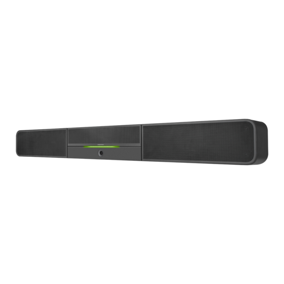
UC-SB1-FLEX and UC-SB1-CAM-FLEX
UC Video Conference Smart Soundbars
Crestron® UC Video Conference Smart Soundbars (UC-SB1-FLEX and UC-SB1-CAM-FLEX) are designed for use with Microsoft Teams® Rooms
systems to facilitate conferencing in small to medium-sized meeting spaces with a built-in microphone, speakers, and camera (UC-SB1-CAM-FLEX
only).
NOTE:
With the exception of the integrated camera, the UC-SB1-FLEX and UC-SB1-CAM-FLEX have similar features. For simplicity within this
guide, the term "soundbar" is used for both models except where noted.
Check the Box
Item
UC-SB1-FLEX and UC-SB1-CAM-FLEX
Anchor, Drywall, Plastic, 3/8 in. x 1/2 in. (P/N 2052565)
Cable, USB 3.0, A - B, 6 ft (1.83 m) (P/N 2053077)
Foot, 2.3 in. x 0.96 in. x 0.15 in., Rubber (P/N 2052169)
Key, Anchor (P/N 4529654)
Power Cord (P/N 2052498)
Screw, 8-AB x 1-1/2 in., Pan Head, Combo (P/N 2052567)
Template, Overlay (P/N 4529513)
Install the Soundbar
The soundbar can be placed on a flat surface or mounted on a wall. The soundbar has the following dimensions:
Dimensions (UC-SB1-CAM-FLEX shown)
3.90 in.
(99 mm)
43.60 in.
(1107 mm)
Place on a Flat Surface
If placing the soundbar on a flat surface, attach the included rubber feet to the bottom of the soundbar as shown in the following diagram.
Attach Rubber Feet (UC-SB1-FLEX shown)
Attach feet here
Qty
1
4
1
2
1
1
4
1
4.57 in.
(116 mm)
Mount on a Wall
The soundbar includes anchors that are suitable for use on sheetrock walls up to 1/2 in. thickness. Masonry and other materials may require
additional installer-supplied mounting hardware.
NOTES:
•
For optimal viewing results, the UC-SB1-CAM-FLEX should be mounted in a location that places the camera approximately 12 in. above the
plane of the room's conference table.
•
When mounting on a wall beneath a display device, leave 3/4 in. (minimum) clearance above the top of the soundbar. Use the included
template to allow for sufficient clearance between the soundbar and display device.
The following tools are required to mount the soundbar:
•
Drywall saw (not included)
•
Drill with 5/16 in. bit (not included)
To mount the soundbar on a wall:
1.
The included template provides drill hole locations for the wall mount hardware. Using the center reference hole of the template as a guide,
attach the template to the desired mounting location with the center reference line of the template at the center of the desired location.
NOTE:
The cutout in the center of the template should provide adequate access for all of the required cabling.
Drill one of these two holes
Cutout for soundbar cables
Drill one of these two holes
Center reference line
2.
Drill two pilot holes on each side of the center reference line as shown in the diagram above. Each side should have one pilot hole drilled in
each row of the template.
3.
Use a drywall saw to make a cutout for the soundbar cables.
4.
Install the four included anchors into the drilled pilot holes.
a.
Fold the anchor in the middle and pinch the ends together.
b.
Insert the anchor in the hole and tap flush with the wall.
Center reference hole
Drill one of these two holes
Drill one of these two holes
c.
Insert the included anchor key to pop the anchor open and lock
it behind a hollow wall.
WARNING:
Do not force or hammer the key.
d.
Drive the screw part of the way into the anchor, leaving
approximately 1/4 in. of the screw exposed.
e.
Repeat steps a through d for the other 3 anchors.
Advertisement

Related Manuals for Crestron UC-SB1-FLEX


Summary of Contents for Crestron UC-SB1-FLEX
- Page 1 The soundbar includes anchors that are suitable for use on sheetrock walls up to 1/2 in. thickness. Masonry and other materials may require only). additional installer-supplied mounting hardware. NOTE: With the exception of the integrated camera, the UC-SB1-FLEX and UC-SB1-CAM-FLEX have similar features. For simplicity within this NOTES: guide, the term “soundbar” is used for both models except where noted. •...
- Page 2 Ce produit est homologué selon les normes et les exigences UL applicables par Intertek Prestations de service. • Reorient or relocate the receiving antenna. document to refer to either the entities claiming the marks and names or their products. Crestron disclaims any proprietary • Increase the separation between the equipment and receiver.
Need help?
Do you have a question about the UC-SB1-FLEX and is the answer not in the manual?
Questions and answers