Table of Contents
Advertisement
Product Description
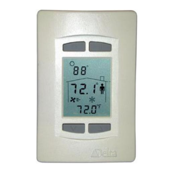
The BACstat II is a line of network room sensors/thermostats with a custom
LCD display and pushbutton interface. They can communicate directly on a
BACnet MS/TP network or Delta's proprietary LINKnet network.
They are capable of displaying a wide-range of digital or analog values,
including setpoints, temperature, air flow, heating and cooling status, fan
speed, valve and damper position, and more. When connected on a BACnet
MS/TP network they function as independent BACnet sensors or thermostats.
When connected to a Controller on a LINKnet network they provide
programmable remote sensor and expanded I/O capabilities. BACstats that are
hardware revision 4 or greater can be flash loaded over the network, and have
termination resistors that are jumper selectable.
The DNS-24 models are network sensors they have multiple onboard sensor options including temperature
Humidity, CO2 and motion, but do not have any outputs or internal control algorithms. The DNT-T103 has 1
extra input, 3 binary outputs and a number of built-in application control strategies. The DNT-T221 has 2
extra inputs, 2 analog and 1 binary output and built-in application control strategies. As a result, DNT
BACstats are capable of stand-alone control when directly connected on an MS/TP network.
Contents
Other Relevant Documents .................................................................................................. 2
Important Information .......................................................................................................... 2
SETUP & CONFIGURATION ............................................................................................................. 2
N
ETWORK
D
EVICE
S
ERVICE
I
NPUT
I
NPUT
SOFTWARE & PROGRAMMING...................................................................................................... 9
O
BJECTS
P
ROGRAMMING
Control Functions ................................................................................................................... 13
O
VERVIEW
S
OFTWARE
S
ETPOINTS
C
ONTROL
C
ONTROL
O
UTP UT
Ows Functions .............................................................................................................................. 34
A
PPENDIX
A
PPENDIX
Document Edition 4.2
Delta Network Sensor / Thermostat: BACstat II
C
........................................................................................................... 2
OMMUNICATIONS
C
(K
) .................................................................................................. 2
ONFIGURATION
EYPAD
T
M
(K
) ....................................................................................................... 7
OOL
ODE
EYPAD
C
.......................................................................................................................... 8
ALIBRATION
S
R
...................................................................................................................... 8
CALE
ANGES
............................................................................................................................................ 9
............................................................................................................................... 12
...................................................................................................................................... 13
L
C
....................................................................................................... 15
OOP
ONTROLLER
...................................................................................................................................... 19
D
........................................................................................................................ 20
IAGRAM
A
(M
, VAV, VVT, HPU, FCU, R
PPLICATIONS
UX
F
& T
......................................................................................................... 29
UNCTIONS
YPES
A: P
N
.................................................................................................... 31
ROGRAMMING
OTES
B: LINK
......................................................................................................................... 32
NET
A
PPLICATION
DNS-24, DNT-T103 & DNT-T221
Document Edition 4.2
, H
) ............................................ 21
AD
UM
G
UIDE
Page 1 of 43
Advertisement
Table of Contents

Related Manuals for Delta Controls DNS-24


Summary of Contents for Delta Controls DNS-24
- Page 1 4 or greater can be flash loaded over the network, and have termination resistors that are jumper selectable. The DNS-24 models are network sensors they have multiple onboard sensor options including temperature humidity, CO2 and motion, but do not have any outputs or internal control algorithms. The DNT-T103 has 1 extra input, 3 binary outputs and a number of built-in application control strategies.
- Page 2 ORCAview, DCU, and Application Controllers, certain BACstat capabilities require support in the other products. The firmware for hardware revision 4 (or greater) DNS-24, DNT-T103 and the DNT-T221 can be flash loaded over the network. V3.22 F &...
- Page 3 Delta Controls When the text is displayed you are being prompted for the valid PIN or access code, a pre- configured 4-digit code, which you must enter before you can gain access to the Configuration Menu. The buttons on the left side of the BACstat have a value of 0, while the buttons on the right side have a value of 1.
- Page 4 DNS-24, DNT-T103 & DNT-T221 Application Guide ONFIGURATION PTIONS The Configuration Menu is a list of items that you can navigate through to make changes for setup purposes. The Configuration Menu items are as follows: Menu Item Description Displayed momentarily to indicate you have successfully entered the Configuration Menu.
- Page 5 Delta Controls Menu Item Description The LCD Display Code Setting (AV15), a 4-digit value (ABCD) configures local display and button handling as follows: Line 1 (Top Left – i.e., Outside Value): 1 to 4 - Disabled - Value from AV5 (i.e., remote value such as OAT) - Value from AI2 (i.e., external sensor)
- Page 6 DNS-24, DNT-T103 & DNT-T221 Application Guide Menu Item Description The Service Tool Mode access setting (AV32) has the following options: Disables all access to Service Tool Mode Provides limited access for VAV, or full access for other applications Provides full access with advanced Air Balancer functions for VAV ...
- Page 7 Delta Controls SERVICE TOOL MODE (KEYPAD) A new BACstat II Quick Reference Card for Service Tool Mode (product number REF-817) is available for quick and easy reference, and for navigation of the Service Tool features. One is shipped with the product, and additional copies can be ordered as necessary.
- Page 8 DNS-24, DNT-T103 & DNT-T221 Application Guide Air Balancer Menu Options Menu Description Item To enter Air Balancing mode, which is only an option when VAV is selected as the Application in the Configuration Menu. To exit Service Tool mode (Yes or No). At any time within the Service Tool...
- Page 9 Fixed whenever the HUM (optional) application is enabled. Built-in 0-2000ppm CO2 Sensor Only available on DNS-24 models On/off Built-in motion sensor Only available on DNS-24 models Unless inputs are multiplexed, many of the input units and associated scale ranges are automatically set when a built-in application is selected.
- Page 10 DNS-24, DNT-T103 & DNT-T221 Application Guide AV6 Day Setpoint Room Setpoint ºC = 21; ºF = 71; % = 30 AV7 Day Minimum Minimum Adjustable Day Setpoint ºC = 18; ºF = 65; % = 20 AV8 ...
- Page 11 Delta Controls CO2 (AI4) On BACstats with the on board carbon dioxide (CO2) sensor option (C), the CO2 sensor shows up as analog input 4. When configured as a LINKnet device with display code 1111 input scaling is done in the parent controller (see Appendix B LINKnet).
- Page 12 DNS-24, DNT-T103 & DNT-T221 Application Guide Out of Sole Master Invalid state Invalid frame Minimum Token cycle time (ms) Maximum Token cycle time (ms) Average Token cycle time (ms) COV subscription failure System Log (AV35) The Description field in this object provides a log of the ten most recent events from the least to the most recent.
- Page 13 Delta Controls PROGRAMMING MS/TP CONNECTION Objects All of the existing predefined BACstat II objects are readily accessible over the MS/TP network. Control Applications BACstats with I/O may be configured to run one of six possible built-in control applications. Another option disables local control altogether.
- Page 14 DNS-24, DNT-T103 & DNT-T221 Application Guide Refer to the Application section of this guide for further detail on each of these control strategies, on page 21. *Although possible, this is not recommended because it can cause excessive network traffic. LGORITHM The application control strategy operates in one of the following basic modes, as determined by the Algorithm Mode variable (AV13).
- Page 15 Delta Controls Communications Reset Enable The Alg mode (AV13) variable also has a property represented by a Comm Reset Enable checkbox in the object dialog. This can be enabled or disabled, depending on installation requirements. Disabled Enabled (the default as of Release 3 Firmware) ...
- Page 16 DNS-24, DNT-T103 & DNT-T221 Application Guide Software Controller Loop ENERAL The operation of the BACstat II is centered around a software controller. The controller uses the following parameters in its operation. Parameter Object Default Value Notes Room Temperature Input 1 **...
- Page 17 Delta Controls ONTROLLER PERATION NORMAL CONTROLLER ACTION 100% -100% Controller Controller Output Output Differential (Heating) (Cooling) Deadband Heating Cooling Temperature Proportional Band Proportional Band Heating Cooling Setpoint Setpoint Day Setpoint Deadband is a span of 0.2 around setpoint (heating or cooling) over which neither heating nor cooling takes place.
- Page 18 DNS-24, DNT-T103 & DNT-T221 Application Guide WITH BOX MODE = HEATING 200% Differential Auxilary Heating 100% Flow Damper Controller Deadband Output Temperature Proportional Band Proportional Band Heating Cooling Setpoint Setpoint Day Setpoint For VAV or VVT applications, when the Box Mode is changed to heating, cooling is inverted and used for controlling the flow damper as the first stage of heating, and the null zone is placed on the far right.
- Page 19 Delta Controls ESET CTION ESET ATE IN REPEA TS PER HOUR If the Reset Rate is non-zero, reset action is enabled. As long as there is a difference (or error) between the input value (i.e., space temperature) and setpoint value, reset action will increment or decrement the Controller Status value (AV14) over time - in proportion to the value of the reset rate and the magnitude of the error - in an attempt to remove the error.
- Page 20 DNS-24, DNT-T103 & DNT-T221 Application Guide Day Differential (AV9) – This is the differential setting between the Day Setpoint and the internal Heating Setpoint (which is used for heating control), and between the Day Setpoint and the internal Cooling Setpoint (which is used for cooling control).
- Page 21 Delta Controls CONTROL DIAGRAM The following diagram displays occupied mode and helps illustrate the relationship between the internal software loop controller and various objects, including outputs. Output 1 Binary (Dir or Rev) PWM (Dir or Rev) Heating ...
- Page 22 DNS-24, DNT-T103 & DNT-T221 Application Guide Outputs 1 and 2 configured as a Tri-State pair require that the “Tri-State Runtime” (AV24) be configured for the associated Tri-State actuator. The default of 120 seconds is suitable for certain Honeywell actuators.
- Page 23 Delta Controls Setup Parameters Setup Variable Function Notes AV24 Tri-state Flow Damper Runtime Default of 120 seconds AV25 Air Flow Factor Converts Duct size and Air flow velocity to CFM or Liters/Second AV26 Air Flow Minimum Minimum Air Flow Setpoint...
- Page 24 DNS-24, DNT-T103 & DNT-T221 Application Guide VVT – [Application (AV12) = 2] Function: Control of a simple VVT box with a Tri-State damper on Outputs 1 and 2 (for DNT-T103) or an analog damper on Output 1 (for DNT-T221), and various options on the remaining outputs (of which some options are no longer available in Release 3 firmware).
- Page 25 Delta Controls Sequence of Operation The current damper position is generated from the Cooling Minimum setpoint, Cooling Maximum Setpoint and the Cool 1 value. Max Damper Position Damper Position Damper Position Damper Position Controller Output (Cooling 1) 100% For the DNT-T103 the desired damper position is compared to the current estimated damper position by the Tri-State controller loop.
- Page 26 DNS-24, DNT-T103 & DNT-T221 Application Guide DNT-T221 I/O (Outputs 1 & 2 are Analog, and Output 3 is a Triac) Input AI1 Input AI2 Input AI3 Remote AV5 Output 1 Output 2 Output 3 Room Temp. Optional OAT Compressor Reversing...
- Page 27 Delta Controls If the Heating and Cooling controllers are both zero the control logic is in deadband and the compressor output is turned O If the Heating controller value exceeds 90% the control logic will switch to heating, and the reversing if isn’t on already.
- Page 28 DNS-24, DNT-T103 & DNT-T221 Application Guide Setup Parameters Setup Variable Function Notes AV24 PWM minimum value or Binary On Delay or Depends on OP1 configuration Actuator Runtime (Tri-State Valves) AV25 PWM maximum value Depends on OP1 configuration AV26 PWM minimum value or Binary On Delay...
- Page 29 Delta Controls Setup Parameters Setup Variable Function Notes AV24 PWM minimum value or Binary On Delay Depends on OP1 configuration or Actuator Runtime (Tri-State Valves) AV25 PWM maximum value Depends on OP1 configuration AV26 PWM minimum value or Binary On Delay...
- Page 30 DNS-24, DNT-T103 & DNT-T221 Application Guide OUTPUT FUNCTIONS & TYPES Regardless of model, any triac outputs are capable of switching up to 24 VAC at a maximum of 0.5 A each, and may be configured for any of a number of output functions and types. Only the DNT-T221 supports two 0-10v outputs, up to a maximum of 20 mA each.
- Page 31 Delta Controls Box Mode affects how the flow damper functions in both VAV and VVT applications. Refer to page 15 for operating information on Box Mode, and page 16 regarding Controller Operation. OWS Configuration It is of course possible to configure the outputs via ORCAview OWS, rather than through the keypad Configuration Menu at the BACstat.
- Page 32 DNS-24, DNT-T103 & DNT-T221 Application Guide Physical Output Associated Output AV Min. Setup Variable Max. Setup Variable AV24 AV25 AV26 AV27 AV28 AV29 The value (in seconds) is shifted by two decimal places when entered in the variable. Default values are,...
- Page 33 Delta Controls Heating Controller Limiting Setup variable AV29 is used as a heating controller limit. A value of 0 to 100% entered into this variable will limit the main heating controller accordingly, and by default is set to 100%. By limiting the controller value itself you are able to limit the output staging, which may be used for load limiting purposes.
- Page 34 DNS-24, DNT-T103 & DNT-T221 Application Guide When the application is set to HPU on a DNT-T103 and the fan type is Intermittent, the fan will start when the compressor starts. When the compressor stops and the Output 3 Binary Delay (AV28) has timed out, the fan output will be turned off.
- Page 35 Delta Controls 2: AV22 (refer to page 30, and associated Application UTPUT ONFIGURATION information) 3: AV23 (refer to page 30, and associated Application UTPUT ONFIGURATION information) : AV24 to AV29 (as per associated Application information) DDITIONAL ARAMETERS...
- Page 36 DNS-24, DNT-T103 & DNT-T221 Application Guide AVIGATOR IGHT OUSE LICKS By clicking the right-mouse button on the BACstat icon in the left pane of Navigator you gain access to a number of device commands. Command : The clear database feature (YES or NO) resets the configuration settings to the CLEAR DATABASE default.
- Page 37 Delta Controls APPENDIX A: Programming Notes The following provides additional important programming information. (AV12 & AV21-23): These variables should never be ONFIGURATION ARIABLES commanded on the fly from a GCL+ program (or user command). They must be configured in the proper sequence and they radically alter operation too much to make frequent changes.
- Page 38 DNS-24, DNT-T103 & DNT-T221 Application Guide APPENDIX B: LINKnet Configuration Menu Options Menu Item DSP On LINKnet BACstats communicate at 76,800 bps. Refer to the Working with MS/TP and LINKnet appendix within the Technical Reference Manual. Menu Item Add On LINKnet, this address is the physical address for the device (limited to 1 to 12) and the other address settings are irrelevant.
- Page 39 Delta Controls An LCD object is automatically created for each BACstat connected to the LINKnet network. However, the associated AI objects representing the room temperature in each BACstat must be created manually, and must follow a predefined numbering scheme. For DAC products the LINKnet object instance number is the LINKnet device address (1 to 12) multiplied by 100, plus the MS/TP object instance number.
- Page 40 DNS-24, DNT-T103 & DNT-T221 Application Guide GCL++ Programming All GCL+ programming for BACstats on a LINKnet network is written in the Application Controller that the BACstats are connected to, using the mapped objects resident in the Application Controller. The LCD object is used for display and button handling. The mapped AI objects are used for reading values.
- Page 41 Delta Controls Occupancy = No House/Man (Disabled) The values shown are for V3.30 DAC/DSC firmware. For V3.22 = House only (Unoccupancy) firmware, the values of 1 and 2 = House & Man (Occupancy) are reversed. = Sun icon is turned off Applicable only for V3.22...
- Page 42 DNS-24, DNT-T103 & DNT-T221 Application Guide be desirable for certain applications). If the user tries to do an override at the stat it will be over-written the next time the program in the DAC is executed (possibly within split-seconds). The following program is the same as above, except that the command for either occupancy or unoccupancy is only sent when the SCH1 changes.
- Page 43 Delta Controls GCL+ P & K : In GCL+ programming you can evaluate the ROGRAMMING RESS ALUES KeyPress object to determine which BACstat button has been pressed, or any 2-button combination. Where two buttons are pressed, the first button pressed represents the last digit and the second button pressed represents the first (hundreds) digit of a 3 digit number.
Need help?
Do you have a question about the DNS-24 and is the answer not in the manual?
Questions and answers
I was looking for temp display on DNS-24 Tstat. Meaning for the Temp reading
The Delta Controls DNS-24 thermostat displays temperature as one of the digital or analog values on its custom LCD screen. It can show room temperature and setpoints in degrees Celsius (°C) or Fahrenheit (°F), such as 21°C or 71°F.
This answer is automatically generated