Delta Controls DNT-T103 Application Manual
Delta network thermostat: bacstat ii
Hide thumbs
Also See for DNT-T103:
- Installation manual (12 pages) ,
- Application manual (35 pages) ,
- Application manual (44 pages)
Table of Contents
Advertisement
Product Description
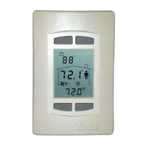
The DNT-T103 and the DNT-T221 are intelligent room thermostats with
custom 3-value, 96 segment, LCD displays. The DNT products can
communicate directly on a BACnet MS/TP network or Delta's proprietary
LINKnet network.
They are capable of displaying a wide-range of digital or analog values,
including setpoints, temperature, air flow, heating and cooling status, fan
speed, valve and damper position, and more. When connected on a BACnet
MS/TP network the DNT-T103 and T221 function as independent BACnet
thermostats. When connected to a Controller on a LINKnet network they
provide programmable remote sensor and expanded I/O capabilities. This
version's firmware can be flash loaded over the network, and have
termination resistors that are jumper selectable.
The DNT-T103 has 1 extra input, 3 binary outputs and a number of built-in application control strategies. The
DNT-T221 has 2 extra inputs, 2 analog and 1 binary output and built-in application control strategies. As a
result, these BACstats are capable of stand-alone control when directly connected on an MS/TP network.
Contents
OTHER RELEVANT DOCUMENTS .................................................................................................. 2
IMPORTANT INFORMATION .......................................................................................................... 2
SETUP & CONFIGURATION ............................................................................................................. 2
SOFTWARE & PROGRAMMING...................................................................................................... 9
CONTROL FUNCTIONS ................................................................................................................... 12
S
OWS FUNCTIONS .............................................................................................................................. 33
Document Edition 4.1
........................................................................................................... 2
) ....................................................................................................... 7
.......................................................................................................................... 8
...................................................................................................................... 8
............................................................................................................................................ 9
............................................................................................................................... 12
...................................................................................................................................... 12
L
C
....................................................................................................... 15
OFTWARE
OOP
ONTROLLER
...................................................................................................................................... 18
........................................................................................................................ 19
......................................................................................................... 28
......................................................................................................................... 32
A
PPLICATION
Delta Network Thermostat: BACstat II
DNT-T103 & DNT-T221
) .................................................................................................. 2
.................................................................................................... 31
G
UIDE
Document Edition 4.1
) ............................................ 20
Page 1 of 41
Advertisement
Table of Contents

Related Manuals for Delta Controls DNT-T103


Summary of Contents for Delta Controls DNT-T103
-
Page 1: Table Of Contents
The DNT-T103 has 1 extra input, 3 binary outputs and a number of built-in application control strategies. The DNT-T221 has 2 extra inputs, 2 analog and 1 binary output and built-in application control strategies. As a result, these BACstats are capable of stand-alone control when directly connected on an MS/TP network. -
Page 2: Other Relevant Documents
BACstat II DNT-T103 and the DNT-T221 products. Although BACstat firmware is independent from ORCAview, DCU, and Application Controllers, certain BACstat capabilities require support in the other products. The firmware for the DNT-T103 and the DNT-T221 can be flash loaded over the network. - Page 3 Delta Controls • When the text is displayed you are being prompted for the valid PIN or access code, a pre- configured 4-digit code, which you must enter before you can gain access to the Configuration Menu. The buttons on the left side of the BACstat have a value of 0, while the buttons on the right side have a value of 1.
- Page 4 DNT-T103 & DNT-T221 Application Guide ONFIGURATION PTIONS The Configuration Menu is a list of items that you can navigate through to make changes for setup purposes. The Configuration Menu items are as follows: Menu Item Description Displayed momentarily to indicate you have successfully entered the Configuration ...
- Page 5 Delta Controls Menu Item Description The LCD Display Code Setting (AV15), a 4-digit value (ABCD) configures local display and button handling as follows: Line 1 (Top Left – i.e., Outside Value): 1 to 4 - Disabled - Value from AV5 (i.e., remote value such as OAT) - Value from AI2 (i.e., external sensor)
- Page 6 DNT-T103 & DNT-T221 Application Guide Menu Item Description The Service Tool Mode access setting (AV32) has the following options: Disables all access to Service Tool Mode Provides limited access for VAV, or full access for other applications Provides full access with advanced Air Balancer functions for VAV Time Clock feature allows the ability for a signal from an external source to directly ...
-
Page 7: Service Tool Mode (Keypad)
Delta Controls : AI2 (and AI3 for the DNT-T221) are not configured through the Configuration Menu. These objects must be configured through the OWS (i.e., for Scale/Units) – except when AI2 is used for VAV airflow. Refer to OWS Functions on page 33 for more information. -
Page 8: Input Calibration
DNT-T103 & DNT-T221 Application Guide Air Balancer Menu Options Menu Description Item do not need to command. [When outputs are defined as tri-state in the Configuration menu, modifications can only be made to the primary output – the other output cannot be modified.] •... -
Page 9: Input Scale Ranges
Input 2 (Available Input) Humidity Input 3 (Humidity on DNT-H103 DNT-H121) Input 3 * Input 3 (Extra Input on DNT-T103 DNT-T221) Output 1 * Output 1 (0 – 100%, Name Changes) Output 2 * Output 2 (0 – 100%, Name Changes) Output 3 * Output 3 (0 –... - Page 10 DNT-T103 & DNT-T221 Application Guide AV11 Night Cool Setpoint Night Setpoint for Cooling ºC = 30; ºF = 86; % = 30 AV12 Application Control Application (Name Changes) None AV13 Alg Mode Algorithm Mode 0 (O or Night)
- Page 11 Delta Controls Receive overrun CRC error MSTP pass token timeout Out of Sole Master Invalid state Invalid frame Minimum Token cycle time (ms) Maximum Token cycle time (ms) Average Token cycle time (ms) COV subscription failure System Log (AV35) The Description field in this object provides a log of the ten most recent events from the least to the most recent.
-
Page 12: Programming
DNT-T103 & DNT-T221 Application Guide PROGRAMMING MS/TP CONNECTION Objects All of the existing predefined BACstat II objects are readily accessible over the MS/TP network. Control Applications BACstats with I/O may be configured to run one of six possible built-in control applications. - Page 13 Delta Controls Refer to the Application section of this guide for further detail on each of these control strategies, on page 20. *Although possible, this is not recommended because it can cause excessive network traffic. LGORITHM The application control strategy operates in one of the following basic modes, as determined by the Algorithm Mode variable (AV13).
- Page 14 DNT-T103 & DNT-T221 Application Guide communication is lost. communication is lost, to try and re-establish communication • If the device resets, the mode reverts to • whatever it was just prior to the reset (i.e., last Should the device reset, the mode is set to...
- Page 15 Delta Controls (DNT-T103 DNT-T221 O When the application control strategy is configured for VAV or VVT, the Box Mode (variable AV33) can be set to either cooling (default) or heating. When set to cooling, the air supply is treated as the first stage of cooling.
- Page 16 DNT-T103 & DNT-T221 Application Guide ONTROLLER PERATION NORMAL CONTROLLER ACTION 100% -100% Controller Controller Output Output Differential (Heating) (Cooling) Deadband Heating Cooling Temperature Proportional Band Proportional Band Heating Cooling Setpoint Setpoint Day Setpoint Deadband is a span of 0.2 around setpoint (heating or cooling) over which neither heating nor cooling takes place.
- Page 17 Delta Controls WITH BOX MODE = HEATING 200% Differential Auxilary Heating 100% Flow Damper Controller Deadband Output Temperature Proportional Band Proportional Band Heating Cooling Setpoint Setpoint Day Setpoint For VAV or VVT applications, when the Box Mode is changed to heating, cooling is inverted and used for controlling the flow damper as the first stage of heating, and the null zone is placed on the far right.
-
Page 18: Setpoints
DNT-T103 & DNT-T221 Application Guide ESET CTION ESET ATE IN REPEA TS PER HOUR If the Reset Rate is non-zero, reset action is enabled. As long as there is a difference (or error) between the input value (i.e., space temperature) and setpoint value, reset action will increment or decrement the Controller Status value (AV14) over time - in proportion to the value of the reset rate and the magnitude of the error - in an attempt to remove the error. - Page 19 Delta Controls Day Differential (AV9) – This is the differential setting between the Day Setpoint and the internal Heating Setpoint (which is used for heating control), and between the Day Setpoint and the internal Cooling Setpoint (which is used for cooling control). The one value is used for both, one on each side of the Day Setpoint.
-
Page 20: Control Diagram
Output 3 Notes: Binary (Dir or Rev) 1. ∗ indicates the output type is only applicable for the DNT-T103. PWM (Dir or Rev) 2. ∗ ∗ indicates the output type is only applicable for the DNT-T221. Time Proportioned (D or R) 3. - Page 21 Function: Control of a simple VAV box with air flow measured with a Kavlico sensor (DFT740-A) or Setra sensor on Input 2 (0 to 1” range), a Tri-State damper on Outputs 1 and 2 (for DNT-T103) or an analog damper on Output 1 (for DNT-T221), and various options on the remaining outputs (some no longer available in Release 3).
- Page 22 DNT-T103 & DNT-T221 Application Guide Setup Parameters Setup Variable Function Notes AV24 Tri-state Flow Damper Runtime Default of 120 seconds AV25 Air Flow Factor Converts Duct size and Air flow velocity to CFM or Liters/Second AV26 Air Flow Minimum Minimum Air Flow Setpoint...
- Page 23 VVT – [Application (AV12) = 2] Function: Control of a simple VVT box with a Tri-State damper on Outputs 1 and 2 (for DNT-T103) or an analog damper on Output 1 (for DNT-T221), and various options on the remaining outputs (of which some options are no longer available in Release 3 firmware).
- Page 24 Controller Output (Cooling 1) 100% For the DNT-T103 the desired damper position is compared to the current estimated damper position by the Tri-State controller loop. The Tri-State damper outputs (1 & 2) are used to control the damper and adjust the estimated position to match the current desired position. The rate of the damper from closed to open is adjusted using AV24 –...
- Page 25 Delta Controls DNT-T221 I/O (Outputs 1 & 2 are Analog, and Output 3 is a Triac) Input AI1 Input AI2 Input AI3 Remote AV5 Output 1 Output 2 Output 3 Room Temp. Optional OAT Compressor Reversing Heating 2 (0/10v) Valve (0/10v) Room Temp.
- Page 26 (FCU) – [Application (AV12) = 4] Function: Control of a simple Fan Coil Unit with fan. DNT-T103 I/O (Outputs 1 to 3 are Triacs) Input AI1 Input AI2 Input AI3...
- Page 27 The selected heating and cooling outputs will operate according to their type and the controller stage that they are associated with. DNT-T103 Only: When the fan type is ‘Intermittent’ the fan will start when the first stage controller value for heating or cooling becomes greater than 99.9%. When the first stage controllers for heating and cooling both become less than 1% a delay counter for stopping the fan will be started.
-
Page 28: Output Functions & Types
DNT-T103 & DNT-T221 Application Guide AV28 PWM minimum value or Binary On Delay Depends on OP3 configuration AV29 PWM maximum value or Time Depends on OP3 configuration Proportioned Heating Controller Limit Sequence of Operation The selected heating outputs will be operated according to their type and the controller stage that they are associated with. - Page 29 (Tri-State) for a tri-state flow damper (DNT-T103 & VAV). Box Mode affects how the flow damper functions in both VAV and VVT applications. Refer to page 14 for operating information on Box Mode, and page 16 regarding Controller Operation.
- Page 30 Maximum PWM Value = 293 (TP) ROPORTIONED The DNT-T103 can have up to two stages of Time Proportioned heat (Outputs 2 and 3), while the DNT-T221 can have one stage (Output 3). These are similar to the PWM outputs except: Page 30 of 41...
- Page 31 100%. By limiting the controller value itself you are able to limit the output staging, which may be used for load limiting purposes. However, this limit is only applicable for heating, not cooling applications. (DNT-T103 O TATE OR LOATING OINT Tri-State uses a pair of outputs (always Outputs 1 and 2).
- Page 32 BACstat is connected to. When the application is set to FCU on a DNT-T103 and the fan type is Intermittent, the fan will start when the first stage controller value for heating or cooling becomes greater than 99.9%. When the first stage controllers for heating and cooling both become less than 1% and the Output 3 Binary Delay (AV28) has timed out, the fan output will be turned off.
-
Page 33: Ows Functions
Delta Controls If the application is something other than VAV or VVT, then both analog outputs may be configured for either heating or cooling. Analog outputs for heating or cooling may be either direct or reverse acting. For the HPU application, 2-position control is provided for the compressor and reversing valve, 0 or 10v (typically requiring an appropriate interface relay), rather than modulating the two analog outputs. - Page 34 DNT-T103 & DNT-T221 Application Guide Additional Settings These are additional settings you may also want to set from the OWS, and may be commanded as necessary, but rarely are once they have been set (or the control loop has been tuned).
-
Page 35: Appendix A: Programming Notes
CTIVE LARMS Loading databases between different models may cause database load failures. For example, DNT-T103 ↔DNT-H103 ↔ DNT-T221, etc. Load This provides the capability of loading a BACstat file (which you have previously saved) into a BACstat, and in so doing will configure it with the settings contained in the file. You can reload the file either back into the source BACstat or into another BACstat. -
Page 36: Appendix B: Linknet
DNT-T103 & DNT-T221 Application Guide APPENDIX B: LINKnet Configuration Menu Options Menu Item DSP On LINKnet BACstats communicate at 76,800 bps. Refer to the Working with MS/TP and LINKnet appendix within the Technical Reference Manual Menu Item Add On LINKnet, this address is the physical address for the device (limited to 1 to 12) and the other address settings are irrelevant. - Page 37 Input 2 * Input 2 (Available Input) AIx03 Humidity Input 3 (Humidity on DNT-H103 DNT-H121) Input 3 * Input 3 (Extra Input on DNT-T103 DNT-T221) Output 1 * Output 1 on DNT-T103 Output 2 * Output 2 on DNT-T103 Output 3 *...
- Page 38 DNT-T103 & DNT-T221 Application Guide With V3.21 Firmware: When connected to LINKnet, local display and button handling should be disabled (i.e., AVx15 = 1111), which is the default when you set the LINKnet Communications Setting to On. This way, the LCD and buttons are fully accessible from the Application Controller for custom programming.
- Page 39 Delta Controls = Fan with Wave 1 & Wave 2 = Fan with Wave 1, Wave 2, Wave 3 Heating = Heating icon is turned off = Heating icon is turned on Cooling = Cooling icon is turned off = Cooling icon is turned on...
- Page 40 DNT-T103 & DNT-T221 Application Guide Programming Notes (LINKnet) The following provides additional important programming information. : When commanding all other variables for LINKnet devices from OMMANDING ARIABLES GCL++ in an Application Controller write your programs so they are not being commanded on every program scan.
- Page 41 Delta Controls Document Edition 4.1 Page 41 of 41...
Need help?
Do you have a question about the DNT-T103 and is the answer not in the manual?
Questions and answers