Advertisement
Quick Links
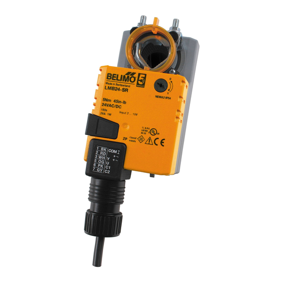
LMB(X)24-SR(-T)
Proportional, Non-Spring Return, 24 V, for 2 to 10 VDC or 4 to 20 mA
Technical Data
LMB(X)24-SR(-T)
Power supply
24 VAC ± 20% 50/60 Hz
24 VDC ± 10%
Power consumption
1.5 W (0.4 W)
Transformer sizing
3 VA (Class 2 power source)
Electrical connection
3 ft, 18 GA plenum rated cable
1/2" conduit connector
protected NEMA 2 (IP54)
3 ft [1m] 10 ft [3m] 16 ft [5m]
Overload protection
electronic throughout 0 to 95° rotation
Operating range Y
2 to 10 VDC, 4 to 20 mA
100 kΩ (0.1 mA), 500 Ω
Input impedance
Feedback output U
2 to 10 VDC (max 0.5 mA)
Angle of rotation
max. 95°, adjustable with mechanical stop
Torque
45 in-lb [5 Nm]
Direction of rotation
reversible with
actuator will move:
=CCW with decreasing control signal (10 to 2V)
=CW with decreasing control signal (10 to 2V)
Position indication
reflective visual indicator (snap-on)
Manual override
external push button
Running time
95 seconds, constant independent of load
Humidity
5 to 95% RH non condensing (EN 60730-1)
Ambient temperature
-22°F to 122°F [-30°C to 50°C]
Storage temperature
-40°F to 176°F [-40°C to 80°C]
Housing
NEMA 2, IP54, UL enclosure type 2
Housing material
UL94-5VA
Agency listings†
cULus acc. to UL 60730-1A/-2-14,
CAN/CSA E60730-1:02,
CE acc. to 2004/108/EEC and 2006/95/EC
Noise level
<35dB(A)
Servicing
maintenance free
Quality standard
ISO 9001
Weight
1.7 lbs [0.5 kg]
LMB(X)24-SR-T
Electrical connection
screw terminal (for 26 to 14 GA wire)
Housing
unprotected (NEMA 1/IP20)
protected (NEMA 2/IP20) use ZS-T
† Rated Impulse Voltage 800V, Type of action 1, Control Pollution Degree 3.
800-543-9038 USA
287
Torque min. 45 in-lb for control of damper surfaces up to 11 sq ft.
Models
LMB24-SR/LMX24-SR
LMB24-SR-T/LMX24-SR-T
Application
For proportional modulation of dampers in HVAC systems. Actuator sizing should be
done in accordance with the damper manufacturer's specifications.
The actuator is mounted directly to a damper shaft from 1/4" up to 5/8" in diameter
by means of its universal clamp. Shafts up to 3/4" diameter can be accommodated by
an accessory clamp.
The actuator operates in response to a 2 to 10 VDC, or with the addition of a
500 Ω resistor, a 4 to 20 mA control input from an electronic controller or positioner.
A 2 to 10 VDC feedback signal is provided for position indication or master-slave
applications.
Operation
The actuator is not provided with and does not require any limit switches, but is
electronically protected against overload. The anti-rotation strap supplied with the
actuator will prevent lateral movement.
The LMB series provides 95° of rotation and a visual indicator indicates position of the
actuator. When reaching the damper or actuator end position, the actuator
automatically stops. The gears can be manually disengaged with a button on the
actuator cover.
The LMB24-SR... actuators use a sensorless brushless DC motor, which is controlled
by an Application Specific Integrated Circuit (ASIC). The ASIC monitors and controls
the actuator's rotation and provides a digital rotation sensing (DRS) function to prevent
damage to the actuator in a stall condition. Power consumption is reduced in holding
mode.
Add-on auxiliary switches or feedback potentiometers are easily fastened directly onto
the actuator body for signaling and switching functions.
switch
Dimensions (Inches [mm])
866-805-7089 CANADA
LMB24-SR.1 (bulk)
LMB24-SR-T.1 (bulk)
1/4" to 3/4" [6 to 20]
5/16" to 3/4" [8 to 26]
3.47" [88]
4.57" [116]
3.7" [94]
0.86" [22]
203-791-8396 LATIN AMERICA
To center of
mounting slot.
2" [50.8]
Advertisement

Related Manuals for Belimo LMB24-SR


Summary of Contents for Belimo LMB24-SR
- Page 1 1/2” conduit connector actuator cover. protected NEMA 2 (IP54) The LMB24-SR… actuators use a sensorless brushless DC motor, which is controlled 3 ft [1m] 10 ft [3m] 16 ft [5m] by an Application Specific Integrated Circuit (ASIC). The ASIC monitors and controls Overload protection electronic throughout 0 to 95°...
- Page 2 If required, actuator will be provided with screw terminal strip for electrical connections (LMB24-SR-T). Run time shall be constant and independent of torque. A 2 to 10 VDC feedback signal shall be provided for position indication.
Need help?
Do you have a question about the LMB24-SR and is the answer not in the manual?
Questions and answers