
Related Manuals for ZKTeco Atlas 00 Series


Summary of Contents for ZKTeco Atlas 00 Series
- Page 1 Installation Guide Atlas x00 Series Access Control Panels Version: 1.0 Date: July, 2019...
-
Page 2: What's In The Box
What’s in the Box 4 Screws & Anchors 1 Screwdriver 4 Diodes Atlas x00 Series Access Control Panels Installation Guide... -
Page 3: Table Of Contents
CONTENTS What’ s in the Box ..............Optional Accessories ............Safety Precautions ..............Product PIN Diagram ............LED Indicators ................Product Dimension ..............Installation of Panel & Cabinet ........Wiring Legend ................ Power Wiring Diagram ............ Wiegand Connection ............OSDP Connection .............. -
Page 4: Optional Accessories
Optional Accessories Wiegand Card Reader Prox Card Door Sensor Exit Button Alarm CR10E Card Enroller Atlas x00 Series Metal Cabinet Atlas x00 Series Access Control Panels Installation Guide... -
Page 5: Safety Precautions
Safety Precautions The following precautions are to keep user’s safe and prevent any damage. Please read carefully before installation. Do not expose to direct sunlight, water, dust and soot. Do not place any magnetic objects near the product. Mag- netic objects such as magnets, CRT, T V, monitors or speakers may damage the device Do not place the device next to heating equipment. -
Page 6: Product Pin Diagram
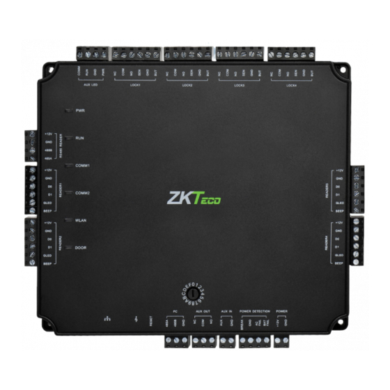
Product PIN Diagram WIFI OSDP Reader Wiegand Wiegand Reader 1 Reader 3 Wiegand Wiegand Reader 2 Reader 4 (POE) Figure 1 The function of reset button (once reset button is pressed, LED will blink fast): Press reset button for about 2-5 seconds, zk firmware will check if there is a USB disk which stores an upgrade package inserted into controller, if yes, then controller will do firmware upgrade automatically. -
Page 7: Led Indicators
LED Indicators LINK Solid Green LED indicates TCP/IP communication is normal Flashing (ACT )Yellow LED indicates data communication is in progress Figure 2 Solid (POWER) Red LED indicates the panel is powered on. Figure 3 Flashing (RUN) Green LED indicates that panel is in normal working state. -
Page 8: Product Dimension
Product Dimension Atlas-100 Atlas-200 Atlas-400 6.3in (160mm) 7.75in (197mm) 7.75in (197mm) Figure 9 Atlas x00 Series Metal Cabinet 11in (280mm) 15in (380mm) 3.15in (80mm) Figure 10 The surface of the metal cabinet is high temperature baking paint, which can prevent rust. Atlas x00 Series Access Control Panels Installation Guide... -
Page 9: Installation Of Panel & Cabinet
Installation of Panel & Cabinet Cable Conduit (Punch hole for cables) Atlas Panel Heat Dissipation Grill Figure 11 Step 1 Step 2 Step 3 Pass the cable through holes Mount the Metal Cabinet Fasten the Atlas Panel with four screws. State Indicators Mounting Holes Figure 12... -
Page 10: Wiring Legend
Wiring Legend OSDP Reader Card Reader The auxiliary input may be connected to infrared motion sensors, fire alarms, or smoke detectors. The auxiliary output may be connected to alarms, cameras or door bells, etc. Figure 13 Atlas x00 Series Access Control Panels Installation Guide... -
Page 11: Power Wiring Diagram
Power Wiring Diagram 12V DC POE Power Supply ETHERNET Figure 14 Atlas x00 Series Access Control Panels Installation Guide... -
Page 12: Wiegand Connection
Wiegand Connection 16 or 18 AWG shielded cable recommended DC+(6-14V) Wiegand D0 Wiegand D1 Green LED Beeper Wiegand Card Reader Figure 15 Atlas x00 Series Access Control Panels Installation Guide... -
Page 13: Osdp Connection
OSDP Connection OSDP Reader Figure 16 Atlas x00 Series Access Control Panels Installation Guide... -
Page 14: Rex Connections
REX Connections 12V DC ( + ) 12V DC ( - ) Separate Power Supply Exit Button Unused IR Sensor Figure 17 Atlas x00 Series Access Control Panels Installation Guide... -
Page 15: Lock Connection
Lock Connection ETHERNET Door Contact Sensor Sensor FR107 Diode 12V DC Normally Closed Lock 12V DC Figure 18 Atlas x00 Series Access Control Panels Installation Guide... -
Page 16: Aux. I/O Connection
AUX. I/O Connection AUX. Input Connection ETHERNET FIRE ALARM 12V DC 12V DC Figure 19 AUX. Output Connection ETHERNET 12V DC Figure 20 Atlas x00 Series Access Control Panels Installation Guide... -
Page 17: Ethernet Connection
Ethernet Connection LAN Connection Important Notes: Both 10Base-T and 100Base-T are supported. This cable distance must be less than 330 ft. (100m). For cable length of more than 330 ft. (100m). use HUB to amplify the signal. ETHERNET CAT5e or CAT6 ethernet cable recommended Figure 21 Direct Connection... -
Page 18: Typical Installation
Installation Diagram Ethernet Communication wire 220/110 V Input Atlas x00 Access Control Bundle CEILING Sensor Electric Lock OUTDOOR INDOOR Exit Button Reader for “In” Door Reader for “Out” Door Figure 23 Atlas x00 Series Access Control Panels Installation Guide... -
Page 19: Troubleshooting
Troubleshooting 1. How do I connect two-way doors? › Connect “Out” door readers as needed, in pairs with “In” door readers according to the follow- ing table. Model “In” Reader Pairs with "Out" Reader 1-door 2-door 5 (RS485 connection) 6 (RS485 connection) 4-door 7 (RS485 connection) 8 (RS485 connection) -
Page 20: Electrical Specifications
Electrical Specifications Notes WORKING POWER SUPPLY Use regulated DC power Voltage (V) 14.4 adaptor only Current (A) ELECTRONIC LOCK RELAY OUTPUT Use regulated DC power Switching voltage (V) adaptor only Switching Current (A) Auxiliary relay output Use regulated DC power Switching voltage(V) adaptor only Switching Current (A) - Page 21 Specifications Communication TCP/IP, OSDP Power Supply 12V DC, 3A Users Capacity 5,000 Event Database Capacity 10,000 transactions, plus unlimited archive downloads LED Indicator Indicator for communication, power, status and prox card Environment 32-113 °F (0-45°C) Operating Humidity 20% to 80% Number of doors controlled Four Door (four door one way and two door two way) Number of readers supported...
- Page 22 Atlas Series Web Management Application Programming Guide Introduction ........................Understanding the Atlas Series Network ..........Initial Controller Setup ..................... Connect the Controller to the Network ............. Complete the Configuration ................Add a User and Test Access ................. Add Secondary Controllers ..................
-
Page 23: Introduction
Introduction Requirements Obtain an available static IP address and configuration from the network administrator. (Optional) Obtain a signed HTTPS certificate. This provides some additional security and avoids web browser warning messages. Supported certificate formats are PEM or PFX. See “Complete the Configuration, ” below. Find out whether using network time protocol (NTP) to automatically update the controller clock over the Internet is possible and acceptable, as well as whether non-standard time servers are used (such as corporate time serv-... -
Page 24: Understanding The Atlas Series Network
Understanding the Atlas Series Network All Atlas Series systems have a single “primary” controller. Many “secondary” controllers may be added to support additional doors. All secondary control- lers maintain a connection to the primary, and the primary provides all data and configuration the secondaries need to operate. -
Page 25: Initial Controller Setup
Initial Controller Setup Connecting Connect the controller to DC power. Connect an ethernet cable directly from your computer to the controller. If your computer is set to use a static IP address, you will need to temporar- ily change it to one in the range 169.254.202.xxx, or to DHCP. If you normally use DHCP, skip this step. - Page 26 Initial Controller Setup Page 1: Language Choose a language. Your choice will be used for this wizard. It will also become the default language of the Web Management Application. This can be changed later in the hardware configuration of the primary controller. Note: For secondary controllers, Language does not affect the Web Management Application.
- Page 27 Initial Controller Setup Page 3: Primary Controller Name (primaries only) The name of the controller will be used for display in the Web Management Ap- plication and in reports. Note: secondary controllers are named when they are connected to the system in the Web Management Application.
- Page 28 Initial Controller Setup Configuration options available depend on the controller model. Each option will involve one or more of the following possibilities. Each possibility determines the function of the card, PIN, or biometric readers connected to the controller. The configuration can be modified during “Complete the Configuration, ” below. In Only - This the most common configuration, where a reader is used to gain entry, but no credentials are required to exit (although an exit button may be configured for opening the door from the inside).
- Page 29 Initial Controller Setup Select your time zone. In most cases you will never need to set the actual time; the controller will get the time from the internet using a technology called NTP. Other situations are discussed, below, under “Complete the Configuration. ” Note: Secondary controllers get their time and time zone from the primary con- troller.
- Page 30 Initial Controller Setup Page 7: Network Interface Settings The important choice here is “Configure IPv4. ” A primary controller must have a static IP address. This is because secondary con- trollers need to know how to find the primary on the network. Additionally, the users need a consistent address to log in to the Web Management Application.
-
Page 31: Connect The Controller To The Network
Wireless Networking: If your controller model supports WiFi, you still need to set up a wired connection, here. You can add your wireless connection once you are logged in to the Web Management Application. See the online help topic, “Administration: Network”. Page 8: Review All your entries are displayed for review. -
Page 32: Complete The Configuration
Registration is required if you ever need to reset your system password, and op- tionally allows ZKTeco to contact you about software updates and other informa- tion. Follow these steps to register for the first time or to update your registration information. - Page 33 Complete the Configuration Fill in the registration information. Asterisks indicate required information. The email address you enter must be able to receive your registration infor- mation. Submit your registration automatically or by email. a. For automatic registration, click button. You will see a Submit Online progress window followed by a success message.
- Page 34 “Remove Secondary, Muster, or Card Enrollment Point” • Change the default connection type for readers (Wiegand, OSDP, or ZKTeco RS-485). These settings are on the sub-controller, and are detailed in the topic, “Hardware Properties”. The defaults vary by model and are listed in the topic, “Models and Configurations”.
- Page 35 Install a Fingerprint Enrollment Reader (optional) If you are using biometric readers, a ZKTeco USB fingerprint enrollment reader must be installed at any computer where fingerprints will be enrolled. Plug the device into any USB port.
-
Page 36: Add A User And Test Access
Add a User and Test Access Go to “Access Users. ” Click on the menu bar. Create Enter the following minimum required information: • First Name • Last Name • (To test cards) Scroll down to “Cards, ” click the button, then enter the number of a card. - Page 37 Add a User and Test Access Then: Go to “Access Users. ” Scroll down to “Access Levels. ” Click the button and select the access level you created, above. Click on the menu bar. Save The card, PIN, and fingerprint you entered should now work to grant access to the specified doors during the specified schedules, assuming you chose a com- patible “Default Mode”...
-
Page 38: Add Secondary Controllers
Add Secondary Controllers Step 1: Initial Setup Follow the instructions under “Initial Controller Setup, ” above, for each controller. This will configure the controller for connection to the network. Step 2: Add the Controller in the Web Management Application Secondary controllers can be automatically found and added by the Web Man- agement Application. -
Page 39: Mobile App
Mobile App ZKTeco provides its “Atlas” mobile app in Apple’s “App Store” and in “Google Play. ” You must authorize each mobile device before it can access your system. In the Web Management Application: Go to “Admin Authorized Mobile Devices. ”... - Page 40 Mobile App A QR code image will be displayed in the “Authorization Code” field. • Leave this open for scanning, below, or • right click the image to save it. You can then email the image to the mobile device user. On the mobile device: Install and run the “Atlas”...
- Page 41 Mobile App You might have to confirm that Atlas may use the camera. The photo viewfinder will appear. Point the square scanning box at any copy of the authorization QR code. A picture will be taken automatically when a QR code is within the box, showing the message, “Authorization code suc- cessfully located.
- Page 42 Mobile App The “Sign In” screen is next. Enter the “Server Address” of the primary Atlas Series controller. Enter your Atlas Series “Username” and “Password. ” Press Sign In Once signed in you will see a list of everything you can do, including view- ing alarms or status and initiating emergency lockdown.
-
Page 43: Special Considerations For Complex Networks
Special Considerations for Complex Networks If all Atlas Series controllers cannot be located on one network subnet, or if Dis- covery is blocked by network restrictions, observe the following. • There is no difference in the way you set up the primary controller. •... - Page 44 Copyright©2019 ZKTECO CO., LTD. All rights reserved.