Fortinet FortiLog FortiLog-800 Quick Start Manual
Fortinet fortilog fortilog-800: quick start
Hide thumbs
Also See for FortiLog FortiLog-800:
- Administration manual (124 pages) ,
- Quick start manual (2 pages)
Table of Contents
Advertisement
Quick Links
Download this manual
See also:
Administration Manual
FortiLog unit LED Indicators
Light Icon
Description
The FortiLog power indicator. The FortiLog unit is
powered on when the light is on.
Warning light. The light is on when a system or
hardware malfunction occurs.
Network activity. The light flashes as network activity is
occurring on the FortiLog unit.
Hard disk activity. The light flashes as log packets are
written to the FortiLog hard disk, and when the FortiLog
unit access the hard disk to generate reports.
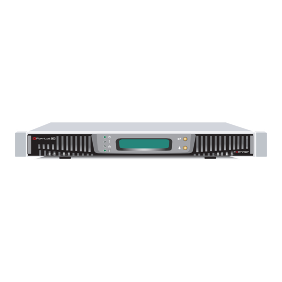
1
Checking the package contents
LED indicators:
Hard Disk
Power, Error, Network,
LEDs
and Disk Access
Connector
Ports 1 and 2
CONSOLE
2
Planning the installation
You can add the FortiLog unit to your local FortiGate network to receive log messages from your local FortiGate units.
You can also connect the FortiLog unit to the FortiGate units remotely through the Internet or using FortiManager.
To connect the FortiLog unit to the FortiGate units remotely, you must configure the DNS server and the default gateway.
To manage the FortiLog unit, you can use a computer within the local network or over the Internet.
Factory Defaults
User name:
Administrator account
Password:
IP:
LAN 1
Netmask:
Management Access:
IP:
LAN 2
Netmask:
Management Access:
3
Connecting the FortiLog unit
•
Place the FortiLog unit on a stable surface. It requires 1.5 inches (3.75 cm)
clearance on each side to allow for cooling.
•
Make sure the power is not plugged into the wall before connecting the power cable.
•
The Status light flashes while the unit is starting up and remains lit when the system
is up and running.
Front
Rack-Mount
Brackets
LCD
Setting
Hard Disk
Panel
Switches
LEDs
A and B
Type
Speed
Protocol Description
RJ-45 10/100/1000Base-T Ethernet
DB-9
9600 bps
RS-232
serial
admin
(none)
192.168.1.99
255.255.255.0
ping, https, ssh, http
192.168.2.99
255.255.255.0
ping, https, ssh, http
FortiLog-800
© Copyright 2005 Fortinet Incorporated. All rights reserved.
Trademarks
Products mentioned in this document are trademarks or registered trademarks of their respective holders.
Regulatory Compliance
FCC Class A Part 15, CE, and UL
09 September 2005
For technical support please visit http://www.fortinet.com.
Check that the package contents are complete.
Back
Power
ATX Redundant
RS-232
SCSI Connector
Connection
Power Supplies
Serial
For Tape Drive
Connection
For Future Use
Connection to the network.
Connection to the management computer.
Provides access to the command line interface (CLI).
Things you need to know before installing the FortiLog unit.
Connect the FortiLog unit to a power outlet and to the network hub or switch.
Power cable connects to power outlet
QuickStart Guide
05-30000-0224-20050909
Power
Switch
Orange - Crossover
Grey - Straight-through
Ethernet Network
Connections
Copyright 2005 Fortinet Incorporated. All rights reserved.
Trademarks
Products mentioned in this document are trademarks.
Documentation
Internet
Straight-through Ethernet cable connects
to hub or switch on the network
FortiLog-800
Null modem cable connects
to serial port on management computer
Ethernet Cables:
Null-Modem Cable
(RS-232)
Power Cable
FortiLog-800
QuickStart Guide
Advertisement
Table of Contents

Subscribe to Our Youtube Channel
Related Manuals for Fortinet FortiLog FortiLog-800


Summary of Contents for Fortinet FortiLog FortiLog-800
-
Page 1: Checking The Package Contents
The Status light flashes while the unit is starting up and remains lit when the system is up and running. FortiLog-800 © Copyright 2005 Fortinet Incorporated. All rights reserved. Trademarks Products mentioned in this document are trademarks or registered trademarks of their respective holders. -
Page 2: For More Information
Fortinet Knowledge Center The knowledge center contains short how-to articles, FAQs, technical notes, product and feature guides, and much more. Visit the Fortinet Knowledge Center at http://kc.forticare.com. Use the web-based manager or the Command Line Interface (CLI) to configure the FortiLog unit IP address, netmask, DNS server IP address, and default gateway IP address.
Need help?
Do you have a question about the FortiLog FortiLog-800 and is the answer not in the manual?
Questions and answers