Table of Contents
Advertisement
Quick Links
Download this manual
See also:
Administration Manual
FortiLog unit LED Indicators
LED
State
Description
Power
On
The FortiLog unit is powered on.
Off
The FortiLog unit is powered off.
LAN
Flashing
Network activities at this interface.
(back)
Off
No link at the interface.
Error
On
The FortiLog unit is in error condition.
Off
The FortiLog unit is running normally.
Network
Flashing
Network activities on the FortiLog unit.
(front)
Off
No network activities.
Disk
Flashing
Hard disk activities.
access
Off
No hard disk activities.
1
Checking the package contents
The FortiLog units are network appliances that you can use to collect and analyze
FortiGate log messages.
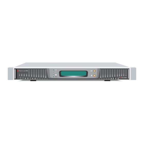
The FortiLog family includes three models. Check the model number on the front panel
of your FortiLog unit. All three models are shown in the picture here.
•
FortiLog-100, desktop model with one hard drive.
•
FortiLog-400, desktop model with four hard drives.
•
FortiLog-800, rackmount model with four hard drives.
Connectors
Connector
Type
Speed
LAN for FortiLog-100
RJ-45 10/100Base-T
LAN1 for FortiLog-400
(FortiLog-100 and
and 800
400)
10/100/1000Base-T
(FortiLog-800)
CONSOLE
DB-9
9600 bps
(FortiLog-800 only)
2
Planning the installation
You can add the FortiLog unit to your local FortiGate network to receive log messages
from your local FortiGate units.
You can also connect the FortiLog unit to the FortiGate units remotely through the
Internet.
To connect the FortiLog unit to the FortiGate units remotely, you must configure the
DNS server and the default gateway.
To manage the FortiLog unit, you can use a computer within the local network or over
the Internet.
Factory Defaults
User name:
Administrator
account
Password:
IP:
LAN
Netmask:
Management Access:
3
Connecting the FortiLog unit
•
Place the unit on a stable surface.
•
If you have a FortiLog-800 unit, you can also mount it in a 19-inch rack. The units require 1.5 inches (3.75 cm) clearance on each side to allow for cooling.
•
Make sure the power switch on the back of the unit is turned off before connecting the power and network cables.
FortiLog-100
Straight-through Ethernet cable connects
to hub or switch on the network
Power cable connects to power supply
Check that the package contents are complete.
Protocol Description
Ethernet
Connection to the network.
RS-232
Connection to the
serial
management computer.
Provides access to the
command line interface (CLI).
Things you need to know before installing the FortiLog unit.
admin
(none)
192.168.1.99
255.255.255.0
HTTPS, Ping
Connect the FortiLog unit to a power outlet and to the network hub or switch.
FortiLog-400
Straight-through Ethernet cable connects
LAN2 and LAN3
For Future Use
Power cable
connects to power outlet
FortiLog -100, 400, 800
1
QuickStart Guide
© Copyright 2004 Fortinet Incorporated. All rights reserved.
Trademarks
Products mentioned in this document are trademarks or registered trademarks of their respective holders.
Regulatory Compliance
FCC Class A Part 15, CE, and UL
15 November 2004
For technical support please visit http://www.fortinet.com.
FortiLog-100
Front
1
LCD
Setting Switches
Panel
A and B
Power
Back
Switch
Reset
Switch
LAN
Power
Connection
FortiLog-800
Front
8
LED indicators:
LCD
Hard Disk
Power, Error, Network,
Panel
LEDs
and Disk Access
Back
Power
ATX Redundant
RS-232
SCSI Connector
Connection
Power Supplies
Serial
For Tape Drive
Connection
For Future Use
FortiMail unit
CONSOLE
Internal Network
8
FortiLog unit
4
Management PC
to hub or switch on the network
Power cable connects to power outlet
8
4
01-12000-0083-20041115
FortiLog-400
LED indicators:
Setting
Power, Error, Network,
LCD
Switches
and Disk Access
Panel
A and B
4
Front
Back
Accessories for each model
Ethernet Cables:
Orange - Crossover
Grey - Straight-through
Rack-Mount
Brackets
Null-Modem Cable
for FortiLog-800
Setting
Hard Disk
Switches
LEDs
A and B
AC Adapter
for FortiLog-100
Power
Switch
Power Cable
LAN2
LAN1
For Future Use
(Network
FortiLog-100,400, 800
Connection)
8
USER MANUAL
Copyright 2004 Fortinet Incorporated. All rights reserved.
Trademarks
Products mentioned in this document are trademarks.
Documentation
FortiGate units
Esc
Enter
Esc
Enter
1
2
PWE
FortiGate unit
Esc
Enter
Internet
Esc
Enter
Esc
Enter
FortiGate unit
FortiGate unit
Straight-through Ethernet cable connects
to hub or switch on the network
FortiLog-800
Null modem cable connects
to serial port on management computer
Reset
Switch
Power
Switch
LAN1
(Network Connection)
LAN2 and LAN3
For Future Use
Power
Connection
ATX
Redundant
Power
Supplies
(RS-232)
QuickStart Guide
Management PC
Esc
Enter
FortiGate unit
Advertisement
Table of Contents

Subscribe to Our Youtube Channel
Related Manuals for Fortinet FortiLog FortiLog-100


Summary of Contents for Fortinet FortiLog FortiLog-100
-
Page 1: Checking The Package Contents
Power cable connects to power supply FortiLog -100, 400, 800 © Copyright 2004 Fortinet Incorporated. All rights reserved. Trademarks Products mentioned in this document are trademarks or registered trademarks of their respective holders. -
Page 2: For More Information
2. Restore factory default configuration: execute factoryreset Congratulations! You have set up the FortiLog unit and finished configuring the basic settings. Technical support Fortinet Technical Support Web site: http://support.fortinet.com Fortinet email support: amer_support@fortinet.com For customers in the United States, Canada, Mexico, Latin America and South America.
Need help?
Do you have a question about the FortiLog FortiLog-100 and is the answer not in the manual?
Questions and answers