Siemens SCALANCE M800 Operating Instructions Manual
Simatic net industrial remote communication remote networks
Hide thumbs
Also See for SCALANCE M800:
- Operating instructions manual (72 pages) ,
- Getting started (54 pages) ,
- Getting started (220 pages)
Table of Contents
Advertisement
SIMATIC NET
Industrial Remote Communication
Remote Networks
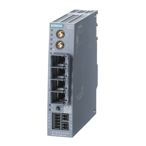
SCALANCE M874, M876
Operating Instructions
08/2018
C79000-G8976-C331-08
___________________
Preface
___________________
Security recommendations
___________________
Description of the device
___________________
Installation
___________________
Connecting up
___________________
Dimension drawings
___________________
Technical specifications
___________________
Approvals
1
2
3
4
5
6
A
Advertisement
Table of Contents


Need help?
Do you have a question about the SCALANCE M800 and is the answer not in the manual?
Questions and answers