Vega VEGAPULS 65 Operating Instructions Manual
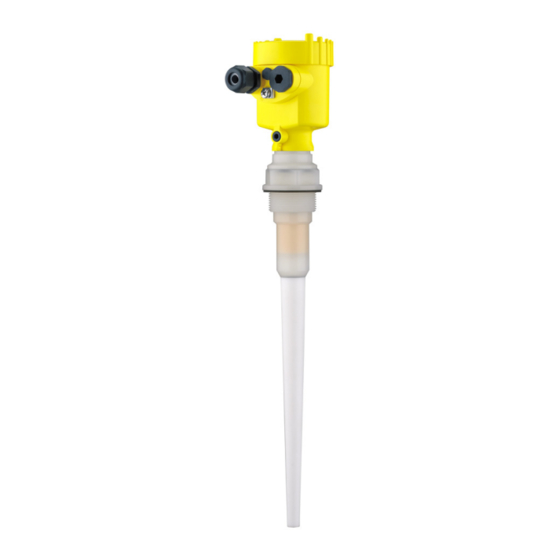
Radar sensor for continuous level measurement of liquids
Hide thumbs
Also See for VEGAPULS 65:
- Operating instructions manual (84 pages) ,
- Quick setup manual (24 pages) ,
- Safety manual (16 pages)

Subscribe to Our Youtube Channel
Related Manuals for Vega VEGAPULS 65


Summary of Contents for Vega VEGAPULS 65
- Page 1 Operating Instructions Radar sensor for continuous level measurement of liquids VEGAPULS 65 4 … 20 mA/HART - two-wire Document ID: 36515...
- Page 2 Set parameters 1. Go via the indicating and adjustment module to the menu "Setup". 2. In the menu item "Medium"you select the medium of your applica- tion, for example "Aqueous solution". VEGAPULS 65 • 4 … 20 mA/HART - two-wire...
- Page 3 2. Select the output characteristics in the menu item "Current out- put". The quick start is then finished. For further information see chapter "Parameter adjustment". VEGAPULS 65 • 4 … 20 mA/HART - two-wire...
-
Page 4: Table Of Contents
Saving the parameter adjustment data ......44 Set up with other systems DD adjustment programs ..........45 Communicator 375, 475 ........... 45 Diagnosis, Asset Management and service Maintenance ..............46 Measured value and event memory ......... 46 VEGAPULS 65 • 4 … 20 mA/HART - two-wire... - Page 5 Please note the Ex-specific safety information for installation and op- eration in Ex areas. These safety instructions are part of the operating instructions manual and come with the Ex-approved instruments. Editing status: 2012-09-27 VEGAPULS 65 • 4 … 20 mA/HART - two-wire...
-
Page 6: About This Document
This arrow indicates a single action. Sequence Numbers set in front indicate successive steps in a procedure. Battery disposal This symbol indicates special information about the disposal of bat- teries and accumulators. VEGAPULS 65 • 4 … 20 mA/HART - two-wire... -
Page 7: For Your Safety
During work on and with the device the required personal protective equipment must always be worn. Appropriate use VEGAPULS 65 is a sensor for continuous level measurement. You can find detailed information on the application range in chapter "Product description". -
Page 8: Ce Conformity
FCC/IC. The instrument is in conformity with RSS-210 of the IC regulations. The instrument may only be used in closed vessels made of metal, concrete, or fibre-reinforced plastic. VEGAPULS 65 • 4 … 20 mA/HART - two-wire... -
Page 9: Environmental Instructions
The environment management system is certified according to DIN EN ISO 14001. Please help us fulfil this obligation by observing the environmental instructions in this manual: • Chapter "Packaging, transport and storage" • Chapter "Disposal" VEGAPULS 65 • 4 … 20 mA/HART - two-wire... -
Page 10: Product Description
For this purpose, move to www.vega.com and "VEGA Tools". Scope of this operating This operating instructions manual applies to the following instrument instructions manual versions: • Hardware from 2.1.0 • Software from 4.5.1 VEGAPULS 65 • 4 … 20 mA/HART - two-wire... -
Page 11: Principle Of Operation
– if necessary, further certificates Principle of operation Application area The VEGAPULS 65 is a radar sensor for continuous measurement of liquids under simple process conditions. It is particularly suitable for level measurement in vessels with small process fittings and under simple process conditions. -
Page 12: Accessories And Replacement Parts
The adjustment is carried out via PACTware/ ® DTM by using the integrated USB connection. You can find further information in the supplementary instructions "PLICSMOBILE T61" (Document-ID 36849). VEGAPULS 65 • 4 … 20 mA/HART - two-wire... - Page 13 VEGAPULS series 60. There is a different version available for each type of signal output. You can find further information in the operating instructions "Elec- tronics module VEGAPULS series 60" (Document-ID 36801). VEGAPULS 65 • 4 … 20 mA/HART - two-wire...
-
Page 14: Mounting
By turning the instrument in the connection flange or mounting boss, the polarisation can be used to reduce the effects of false echoes. The position of the polarisation plane is marked on the process fitting of the instrument. VEGAPULS 65 • 4 … 20 mA/HART - two-wire... - Page 15 Marking hole Installation position When mounting the VEGAPULS 65, keep a distance of at least 500 mm (19.69 in) to the vessel wall. If the sensor is installed in the center of dished or round vessel tops, multiple echoes can arise.
- Page 16 The active part of the antenna, i.e. the conical antenna part should protrude completely out of the socket. To meet the different socket dimensions, sensors for socket lengths up to 50, 100 and 250 mm (2, 4, 10 in) are available. VEGAPULS 65 • 4 … 20 mA/HART - two-wire...
- Page 17 Fig. 9: Recommended socket mounting In case of very big socket diameters, the active antenna part can be slightly recessed in the socket. The following rule applies to the standard version of VEGAPULS 65: Socket diameter corresponds to max. socket height. Sensor orientation Align the sensor in liquids as vertical as possible to the product sur- face to achieve optimum measurement.
- Page 18 If foams are causing measurement errors, the biggest possible radar antenna should be used. As an alternative, sensors with guided microwave can be used. These are unaffected by foam generation and are best suited for such ap- plications. VEGAPULS 65 • 4 … 20 mA/HART - two-wire...
-
Page 19: Connecting To Power Supply
(e. g. 1 nF, 1500 V). The low frequency potential equalisation currents are thus suppressed, but the protective effect against high frequency interfer- ence signals remains. VEGAPULS 65 • 4 … 20 mA/HART - two-wire... -
Page 20: Connecting
4. Remove approx. 10 cm (4 in) of the cable mantle, strip approx. 1 cm (0.4 in) of insulation from the ends of the individual wires 5. Insert the cable into the sensor through the cable entry VEGAPULS 65 • 4 … 20 mA/HART - two-wire... -
Page 21: Wiring Plan, Single Chamber Housing
11. Screw the housing cover back on The electrical connection is hence finished. Wiring plan, single chamber housing The following illustration applies to the non-Ex as well as to the Ex-ia version. VEGAPULS 65 • 4 … 20 mA/HART - two-wire... -
Page 22: Wiring Plan, Double Chamber Housing
Internal connection to the connection compartment For indicating and adjustment module or interface adapter Information: The connection of an external indicating and adjustment unit is not possible with this double chamber housing. VEGAPULS 65 • 4 … 20 mA/HART - two-wire... -
Page 23: Wiring Plan, Double Chamber Housing Ex D
Fig. 18: Electronics compartment, double chamber housing Internal connection to the connection compartment For indicating and adjustment module or interface adapter Internal connection to the plug connector for external indicating and adjust- ment unit (optional) VEGAPULS 65 • 4 … 20 mA/HART - two-wire... -
Page 24: Wiring Plan - Version Ip 66/Ip 68, 1 Bar
Shielding Switch-on phase After connecting the instrument to power supply or after a voltage recurrence, the instrument carries out a self-check for approx. 30 s: • Internal check of the electronics VEGAPULS 65 • 4 … 20 mA/HART - two-wire... - Page 25 As soon as a plausible measured value is found, the corresponding current is outputted to the signal cable. The value corresponds to the actual level as well as the settings already carried out, e.g. factory setting. VEGAPULS 65 • 4 … 20 mA/HART - two-wire...
-
Page 26: Set Up With The Indicating And Adjustment Module
The indicating and adjustment module is powered by the sensor, an additional connection is not necessary. Fig. 22: Insertion of the indicating and adjustment module with single chamber housing into the electronics compartment VEGAPULS 65 • 4 … 20 mA/HART - two-wire... -
Page 27: Adjustment System
Adjustment system Fig. 24: Indicating and adjustment elements LC display Adjustment keys • Key functions [OK] key: – Move to the menu overview – Confirm selected menu VEGAPULS 65 • 4 … 20 mA/HART - two-wire... -
Page 28: Parameter Adjustment
"Setup", "Diagnosis" and "Additional set- tings" are described. The general parameters in these menu section are described in the operating instructions manual "Indicating and adjustment module". VEGAPULS 65 • 4 … 20 mA/HART - two-wire... - Page 29 With this menu item, the sensor can be adapted to the applications. The adjustment possibilities depend on the selection "Liquid" or "Bulk solid" under "Medium". The following options are available when "Liquid" is selected: VEGAPULS 65 • 4 … 20 mA/HART - two-wire...
- Page 30 – Vessel is very often filled and emptied • Vessel: – Socket available – Large agitator blades of metal – Vortex breakers, heating spirals • Process/measurement conditions: – Condensation, buildup by movement VEGAPULS 65 • 4 … 20 mA/HART - two-wire...
- Page 31 – In outside facilities water and snow on the vessel top possible Transportable plastic tank: • Vessel: – Material and thickness different – Measurement through the vessel top • Process/measurement conditions: VEGAPULS 65 • 4 … 20 mA/HART - two-wire...
- Page 32 The following options are available when "Bulk solid" is selected: The following features form the basis of the applications: VEGAPULS 65 • 4 … 20 mA/HART - two-wire...
- Page 33 – Object recognition/monitoring (additional settings required) Through this selection, the sensor is adapted optimally to the applica- tion or the location and measurement reliability under the various basic conditions is increased considerably. VEGAPULS 65 • 4 … 20 mA/HART - two-wire...
- Page 34 To perform the adjustment, enter the distance with full and empty ves- sel, see the following example: VEGAPULS 65 • 4 … 20 mA/HART - two-wire...
- Page 35 2. Edit the percentage value with [OK] and set the cursor to the requested position with [->]. 3. Set the requested percentage value with [+] and save with [OK]. The cursor jumps now to the distance value. VEGAPULS 65 • 4 … 20 mA/HART - two-wire...
- Page 36 The measurement reliability equals signal strength minus noise. The higher the value, the more reliable the measurement. With a function- ing measurement, the values are > 10 dB. VEGAPULS 65 • 4 … 20 mA/HART - two-wire...
- Page 37 Additional adjustments/ The following circumstances cause interfering reflections and can False signal suppression influence the measurement: • High sockets VEGAPULS 65 • 4 … 20 mA/HART - two-wire...
- Page 38 The filling level would then no longer be detectable in this area. If a false signal suppression has already been created in the sensor, the following menu window appears when selecting "False signal suppression": VEGAPULS 65 • 4 … 20 mA/HART - two-wire...
- Page 39 - Reset are reset. The following reset functions are available: Delivery status: Restoring the parameter settings at the time of ship- ment from the factory incl. the order-specific settings. A created false VEGAPULS 65 • 4 … 20 mA/HART - two-wire...
- Page 40 Max. adjustment 0,000 m(d) Damping 0.0 s Current output 4 … 20 mA, < 3.6 mA mode Current output Min. current 3.8 mA, max. current Min./Max. 20.5 mA Lock operation Released VEGAPULS 65 • 4 … 20 mA/HART - two-wire...
-
Page 41: Saving The Parameter Adjustment Data
If it is necessary to exchange a sensor, the indicating and adjustment module is inserted into the replacement instrument and the data are likewise written into the sensor via the menu item "Copy sensor data". VEGAPULS 65 • 4 … 20 mA/HART - two-wire... -
Page 42: Setup With Pactware
250 Ω), an additional external resistance is not necessary. This applies, e.g. to the VEGA instruments VEGATRENN 149A, VEGAMET 381, VEGAMET 391. Common Ex separators are also usually equipped with a sufficient current limitation resistance. In VEGAPULS 65 • 4 … 20 mA/HART - two-wire... -
Page 43: Parameter Adjustment With Pactware
Saving/printing the project as well as import/export functions are also part of the standard version. In the full version there is also an extended print function for complete project documentation as well as a save function for measured value VEGAPULS 65 • 4 … 20 mA/HART - two-wire... -
Page 44: Saving The Parameter Adjustment Data
The standard version is available as a download under www.vega. com/downloads and "Software". The full version is available on CD from the agency serving you. -
Page 45: Set Up With Other Systems
Communicator 375, 475 Device descriptions for the instrument are available as DD or EDD for parameter adjustment with the Field Communicator 375 or 475. The files can be downloaded at www.vega.com/downloads under "Software". VEGAPULS 65 • 4 … 20 mA/HART - two-wire... -
Page 46: Diagnosis, Asset Management And Service
The echo curve of the setup is stored via: • PC with PACTware/DTM • Control system with EDD • Indicating and adjustment module VEGAPULS 65 • 4 … 20 mA/HART - two-wire... -
Page 47: Asset Management Function
Plan in maintenance for the instrument because a failure is expected in the near future (e.g. due to buildup). This status message is inactive by default. It can be activated by the user via PACTware/DTM or EDD. VEGAPULS 65 • 4 … 20 mA/HART - two-wire... - Page 48 – Error in the EEPROM calibration F261 – Error during setup – Repeat setup – False signal suppression – Repeat reset Error in the faulty configuration – Error when carrying out a reset VEGAPULS 65 • 4 … 20 mA/HART - two-wire...
- Page 49 – With the reset to delivery – Repeat reset status, the data could not – Load XML file with sensor Error with the be restored data into the sensor reset delivery status VEGAPULS 65 • 4 … 20 mA/HART - two-wire...
-
Page 50: Rectify Faults
Check the 4 … 20 mA Connect a handmultimeter in the suitable measuring range according signal to the wiring plan. The following table describes possible errors in the current signal and helps to remove them: VEGAPULS 65 • 4 … 20 mA/HART - two-wire... - Page 51 "Hold value" • In case of a too low level indication, the reason could be a line resistance that is too high VEGAPULS 65 • 4 … 20 mA/HART - two-wire...
- Page 52 – Turbulence on the product – Check application parameters, mains momentarily surface, quick filling change if necessary, e.g. in unchanged during fill- dosing vessel, reactor ing and then jumps to time the correct level VEGAPULS 65 • 4 … 20 mA/HART - two-wire...
- Page 53 0 % larger than the product echo, Medium type, Vessel height and during emptying for example, with products with Floor form, adapt if necessary ε < 2.5 oil-based, solvents time VEGAPULS 65 • 4 … 20 mA/HART - two-wire...
-
Page 54: Exchanging The Electronics Module
24 hour service hotline Should these measures not be successful, please call in urgent cases the VEGA service hotline under the phone no. +49 1805 858550. The hotline is also available outside the normal working hours on seven days a week around the clock. -
Page 55: How To Proceed In Case Of Repair
Attach the completed form and, if need be, also a safety data sheet outside on the packaging • Please contact for the return shipment the agency serving you. You can find the agency on our home page www.vega.com. VEGAPULS 65 • 4 … 20 mA/HART - two-wire... -
Page 56: Dismounting
Pass the instrument directly on to a spe- cialised recycling company and do not use the municipal collecting points. These may be used only for privately used products according to the WEEE directive. VEGAPULS 65 • 4 … 20 mA/HART - two-wire... -
Page 57: Supplement
The measured quantity is the distance between process fitting of the sensor and product surface. The reference plane is the seal surface on the hexagon or the lower side of the flange. VEGAPULS 65 • 4 … 20 mA/HART - two-wire... - Page 58 Process reference conditions according to DIN EN 61298-1 Ʋ Temperature +18 … +30 °C (+64 … +86 °F) Ʋ Relative humidity 45 … 75 % Default values, can be assigned individually VEGAPULS 65 • 4 … 20 mA/HART - two-wire...
- Page 59 Time span after a sudden measuring distance change by max. 0.5 m in liquid applications, max 2 m with bulk solids applications, until the output signal has taken for the first time 90 % of the final value (IEC 61298-2). VEGAPULS 65 • 4 … 20 mA/HART - two-wire...
- Page 60 0.2 … 1.5 mm² (AWG 24 … 16) Outside the specified beam angle, the energy of the radar signal has a level which is reduced by 50 % (-3 dB) EIRP: Equivalent Isotropic Radiated Power VEGAPULS 65 • 4 … 20 mA/HART - two-wire...
- Page 61 12 h/24 h Time zone Ex factory Measurement electronics temerature Resolution 1 °C (1.8 °F) Accuracy ±1 °C (1.8 °F) Voltage supply Operating voltage Ʋ Non-Ex instrument 9.6 … 36 V DC VEGAPULS 65 • 4 … 20 mA/HART - two-wire...
- Page 62 Ʋ Aluminium and stainless housing, in- IP 66/IP 68 (1 bar) vestment casting (optionally available) Overvoltage category Protection class The prerequisites for maintaining the protection rating are a suitable cable as well as correct mounting. VEGAPULS 65 • 4 … 20 mA/HART - two-wire...
-
Page 63: Dimensions
Instruments with approvals can have different technical data depending on the version. For that reason the associated approval documents of these instruments must be carefully noted. They are part of the delivery or can be downloaded under www.vega.com and "VEGA Tools" as well as under "Downloads" and "Approvals". - Page 64 Fig. 49: Housing versions in protection IP 66/IP 68 (1 bar) - with integrated indicating and adjustment module the housing is 9 mm/0.35 in higher Single chamber version Double chamber version VEGAPULS 65 • 4 … 20 mA/HART - two-wire...
- Page 65 Thread and hexagon of PVDF for sockets with 50 mm height (inactive length 82 mm, 55/64") Thread and hexagon of PVDF or 316L for sockets with 100 mm height (inactive length 120 mm, 4 23/32") or 250 mm height (inactive length 270 mm, 10 5/8") VEGAPULS 65 • 4 … 20 mA/HART - two-wire...
- Page 66 11 Supplement VEGAPULS 65, flange version ø 33 mm (1.30") Fig. 51: VEGAPULS 65, flange version for sockets with 100 mm height (inactive length 120 mm, 4 23/32") or 250 mm height (inactive length 270 mm, 10 5/8") VEGAPULS 65 • 4 … 20 mA/HART - two-wire...
- Page 67 Les lignes de produits VEGA sont globalement protégées par des droits de propriété intellec- tuelle. Pour plus d'informations, on pourra se référer au site www.vega.com. VEGA lineas de productos están protegidas por los derechos en el campo de la propiedad indus- trial. Para mayor información revise la pagina web www.vega.com.
- Page 68 Error messages 47 Event memory 46 Sensor orientation 17 Service hotline 54 False signal suppression 37 Shielding 19 Fault rectification 50 Socket 16 Functional principle 11 Status messages 47 Storage 12 VEGAPULS 65 • 4 … 20 mA/HART - two-wire...
- Page 69 INDEX Type label 10 Vessel form 34 Vessel height 34 Vessel installations 17 Voltage supply 19 VEGAPULS 65 • 4 … 20 mA/HART - two-wire...
- Page 70 Notes VEGAPULS 65 • 4 … 20 mA/HART - two-wire...
- Page 71 Notes VEGAPULS 65 • 4 … 20 mA/HART - two-wire...
- Page 72 Subject to change without prior notice © VEGA Grieshaber KG, Schiltach/Germany 2012 VEGA Grieshaber KG Phone +49 7836 50-0 Am Hohenstein 113...
Need help?
Do you have a question about the VEGAPULS 65 and is the answer not in the manual?
Questions and answers