Table of Contents
Advertisement
Advertisement
Table of Contents

Related Manuals for Camco 26 dB


Summary of Contents for Camco 26 dB
- Page 2 INFORMATION FOR USE FOR MODELS VORTEX 6, VORTEX 4, VORTEX 2.6 and VORTEX 200V VUM_GB_2005-2008-R4_11-2008 © Copyright 2008 by CAMCO Produktions- und Vertriebs-GmbH für Beschallungs- und Beleuchtungsanlagen Fischpicke 5, D-57482 Wenden, Germany Telephone +49 (0) 2762 408-0 USER MANUAL VORTEX 6, 4, 2.6 and 200V...
-
Page 3: Important Safety Instructions
IMPORTANT SAFETY INSTRUCTIONS 1) Read the information for use (user manual). 2) Please keep this user manual in a safe place during the lifetime of the am- plifi er. The user manual forms an integral part of the amplifi er. Reselling of the amplifi... - Page 4 CAUTION RISK OF ELECTRIC SHOCK DO NOT OPEN THE LIGHTNING FLASH WITH ARROW HEAD SYMBOL, IS INTENDED TO ALERT THE USER TO THE PRESENCE OF UNINSULATED DANGEROUS VOLTAGE WITHIN THE PRODUCT’S ENCLOSURE. THE EXCLAMATION MARK IS INTENDED TO ALERT THE USER TO IMPORTANT INSTRUCTIONS ALSO FOR MAINTENANCE IN THE LITERATURE ACCOMPANYING THE AMPLIFIER.
- Page 5 Please refer to your dealer/distributor. 14. Servicing and Replacement Parts All service and repair work must be carried out by a CAMCO authorised dealer. When replacement parts are required, please ensure that the dealer/distributor only uses replacement parts specifi...
- Page 6 CAMCO Produktions- und Vertriebs-GmbH für Beschallungs- und Beleuchtungsanlagen Manufacturers Address: Fischpicke 5, D-57482 Wenden, Germany Declares that the product with the model name: CAMCO Power amplifi er VORTEX-6, VORTEX-4, VORTEX-2.6 and VORTEX-200V Conforms to the following standards: EN60065 Safety EN55103-1 Emission...
-
Page 7: Table Of Contents
4.6 Fans P.21 4.7 Filter Cleaning P.22 5 OPTIONS 5.1 E.U.I.2(Extended User Interface) 5.1.1 What Are The Possibilities Using The E.U.I.2? 5.2 CAI (CAMCO Audio Interface) 5.2.1 Wiring P.23 5.2.2 CAI Address Settings P.24 5.2.3 CAI Status Indicator P.25 6 TROUBLESHOOTING 6.1 On LED Flashing Sequences... -
Page 8: Welcome To Camco
The success of the LA, DL and DX series power amps has made the CAMCO name synonymous with professional quality, high performance and utterly reliable power amps. -
Page 9: The Amplifi Er
If you have any questions regarding features and/or functions of your VORTEX, CAMCO will be pleased to offer you further information. Alternatively, contact your dealer or distributor. -
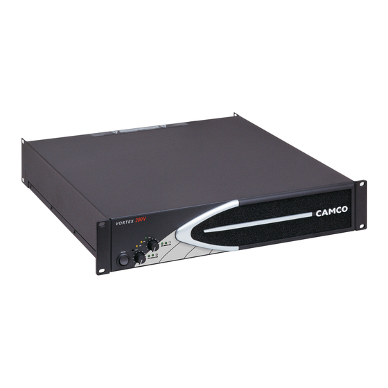
Page 10: Vortex - The Front
2.2 VORTEX – The Rear 7 Removable Air Filter System 12 AC Power Cable 8 Cooling Air Inlet Vents 13 CAMCO Audio Interface (CAI) 9 Enter-Switch (behind Front Panel) 14 SPEAKON Outlets 10 Operating Mode LEDs 15 Cooling Air Outlet Vents... -
Page 11: Factory Settings
VORTEX amplifi ers are delivered with the following factory settings Front panel: On/Off Switch Amplifi er is switched off P.10 USER MANUAL VORTEX 6, 4, 2.6 and 200V Rear panel Input Ground Lift Grounded Optional Feature Circle Mode Stereo Limiter Gain 26 dB... -
Page 12: On/Off Switch
3.1 Mains supply When mounting or connecting the amp always disconnect it from mains. Only connect the VORTEX amplifi er to an appropriate AC circuit and outlet, according to the requirements indicated in the second line on the rating plate. MODEL: MODEL: VORTEX-200 V... -
Page 13: Mounting
Amplifi er switched off Amplifi er switched on (On LED is lighting up) P.12 USER MANUAL VORTEX 6, 4, 2.6 and 200V 3.3 Mounting Use four screws and washers when mounting the amplifi er to the front rack rails. For mobile use, the amplifi er should also be secured using the 19” mounting elements on the rear panel. -
Page 14: Cooling
3.4 Cooling Under normal operation of the power amp, overheating should never be a problem. The air is taken in from the front and out through the back. It is of course essential that while the power amp is running air is able to circulate around it freely. -
Page 15: Mode Selector
3.8 Mode Selector The switch on the rear panel changes the operating mode. Moving this switch will shutdown the amplifi er and restart it in the new operating mode. 3.9 Wiring 3.9.1 E.U.I. and XLR Connection XLR: Pin 1 = Ground (or lifted via 15 Ω resistor) Pin 2 = Hot (inphase) Pin 3 = Cold (out of phase) Always use symmetrical (balanced) shielded cable to connect the amplifi... -
Page 16: Mono-Bridge Operation
mode is useful when, for example, 3 identical loudspeakers are to be operated with the same power. 3.9.4 Mono-Bridge Operation One-channel mono bridged operation. The second channel processes the same input signal, but with reversed phase. The (single) load is connected between the two positive channel outputs using a suitable connected SPEAKON connector. -
Page 17: Controls
WARNING ! SPEAKON connectors marked with the lightning fl ashes indicate high vol- tages that are potentially life threatening. Wiring to these terminals requires installation by an instructed person or the use of ready-made leads or cords. Custom wiring should only be carried out by qualifi ed personnel. To prevent electric shock, do not operate the amplifi... -
Page 18: Gain Selector
This switch on the rear of the VORTEX allows the maximum amplifi cation attainable to be set directly in the input stage. The VORTEX amplifi er has a 26 dB and 32 dB voltage gain setting along with a 1,4 V sensitivity setting. -
Page 19: Signal Leds
4.2.2 Signal LEDs The green Signal LED is illuminated when the voltage level at the output reaches approx. 4 V; this corresponds to a power of approx. 4 W over a 4 Ohm resistor. 4.2.3 Clip LEDs (multifunctional) The colour of the bi-coloured (green/red) LED changes between red, green and yellow depending on the load and the signal modulation conditions. -
Page 20: Speaker Protect Limiter
4.3.4 Speaker Protect Limiter Whenever the SOA protection of the power amp switches back the current rail there could be a small clipping at the output; but the microprocessor is also triggered by this protection and will reduce the signal level immediately to minimise the effect. -
Page 21: Mains Failure Detection
4.4.3 Mains Failure Detection Mains Failure Detection is always operative. When the mains supply is interrupted for about 2 mains cycles, the amplifi er will switch off. When the mains voltage returns to a normal value, a soft start occurs. 4.4.4 Fuse Protection The average mains current can peak temporarily, depending on the load impedance and type of signal, at values several times higher than the nominal... -
Page 22: Filter Cleaning
(4) from the cradle (2) and then carefully pull the CAMCO badge (5) out of the four fastening holes with both hands. Remove the foam fi lter (3) and clean it with a mild dishwashing detergent and warm water. -
Page 23: E.u.i.2(Extended User Interface)
You can use the E.U.I.2 as a fi lter, remote control, signal processing device and more… Please contact your dealer/distributor or CAMCO to customise the E.U.I.2 according to your wishes. 5.2 CAI (CAMCO Audio Interface) CAI is a bus system, in which all signifi cant device functions can be monitored externally and remotely controlled using a master PC. -
Page 24: Cai Address Settings
5.2.2 CAI Address Settings The CAI address selection procedure will not affect the operation of the VORTEX but whilst this procedure is active, the volume cannot be adjusted by using the pots. Briefl y press the Enter-Switch . This push button switch can be accessed through the 3 mm hole in the front panel between the On/Off switch and the LEDs. -
Page 25: Cai Status Indicator
5.2.3 CAI Status Indicator This green LED indicates the presence of communication between PC and the amp. P.24 USER MANUAL VORTEX 6, 4, 2.6 and 200V... -
Page 26: On Led Flashing Sequences
6.1 On LED Flashing Sequences When switching on the amp the On LEDs fl ash twice accompanied by a fl ash of Clip LEDs. This is normal for the ‘Start’ sequence of the VORTEX. When switching off the amp the On LEDs fl ash several times followed by a fl... -
Page 27: Problem: No Sound
Keep the VORTEX Volume Pots at least halfway up and try changing input sensitivity from 1,4 V to 32 dB or 26 dB with the Gain Selector on the rear. -
Page 28: Problem: Hiss
6.6 Problem: Hiss Unplug the amplifi er input to check that the hiss is coming from the source or from a device upstream. Erratic or popping noises indicate an electronic fault in the offending unit. To keep the noise fl oor low, operate the primary signal source at full level, without clipping. - Page 29 Output Power 1 kHz, THD ≤ 0,1 %, in mono-bridge mode 1 kHz, THD ≤ 0,1 %, both channels driven Duration limited by fuse / thermal protection for RL < 8 Ω in stereo mode or RL < 16 Ω in mono-bridge mode. Measurement at 2 Ω...
- Page 30 8 Ω, 10 dB below rated power 40 kΩ balanced Voltage Gain selectable: 26 dB, 32 dB, or 1,4 V input sensitivity inrush-current limitation, temperature monitoring of transformers and heat-sinks, output DC protection, SOA protection, output over current protection, under impedance limiter, intelligent mains fuses protection...
-
Page 31: Measurements
Figure 8.1 Gain vs. frequency (Ch1, Ch2) (Measurements of a typical performance of a VORTEX 6) Figure 8.2 Channel separation vs. frequency @ 10 W / 4 Ω (Ch2 => Ch1, (Measurements of a typical performance of a VORTEX 6) P.30 USER MANUAL VORTEX 6, 4, 2.6 and 200V... - Page 32 Figure 8.5 Output impedance vs. frequency @ 1 Amp RMS injected current (Ch1, Ch2) equivalent 11 mΩ + 2,1 uH (Measurements of a typical performance of a VORTEX 6) -100 -110 -120 100u 200u 500u 1m 10 m 20m Vrms Figure 8.6 THD+N vs.
- Page 33 -100 -110 -120 100u 200u 500u 1m 10m 20m Vrms Figure 8.9 CCIF difference frequency method (10,5 kHz and 11,5 kHz) vs. input level @ 4 Ω (Ch1, Ch2) (Measurements of a typical performance of a VORTEX 6) -100 100u 200u 500u 1m 10m 20m...
- Page 34 5000 3961 4000 2956 2186 3000 1823 2000 1000 Impedance / Ω Figure 8.11 VORTEX 200V (Measurements of a typical performance) 5000 4023 4000 3090 2715 3000 2113 2000 1000 Impedance / Ω Figure 8.12 VORTEX 6 (Measurements of a typical performance) P.33 USER MANUAL VORTEX 6, 4, 2.6 and 200V...
-
Page 35: Summary Of Warranty
9.1 Summary Of Warranty CAMCO guarantees the VORTEX amplifi er to be free from defective material and/or workmanship for a period of six (6) years from the date of sale. When a defect occurs under normal installation and use, CAMCO will repair the product under this warranty. - Page 36 Shipping Address To transport the amplifi er, the original packing materials must be used. Please return the amplifi er to the following address or your nearest CAMCO appointed distributor. CAMCO Produktions- und Vertriebs-GmbH für Beschallungs- und Beleuchtungsanlagen, Fischpicke 5, D-57482 Wenden, Germany P.35...
-
Page 37: Maintenance Information
11 Maintenance Information Cleaning and servicing the inside of the amplifi er must never carry out by un- qualifi ed personnel. The amplifi er must never be opened by unqualifi ed person- nel. Cleaning and servicing work on the inside of the amplifi er must only be carried out by qualifi... - Page 38 Mailing Address: CAMCO Produktions- und Vertriebs-GmbH für Beschallungs- und Beleuchtungsanlagen Fischpicke 5 D-57482 Wenden Germany Telephone: +49 (0) 2762 408-0 Facsimile: +49 (0) 2762 408-10 Internet: www.camcoaudio.com Email: postmaster@camcoaudio.com P.37 USER MANUAL VORTEX 6, 4, 2.6 and 200V...
- Page 39 P.38 USER MANUAL VORTEX 6, 4, 2.6 and 200V...
- Page 40 www.camcoaudio.com...
Need help?
Do you have a question about the 26 dB and is the answer not in the manual?
Questions and answers