Table of Contents
Advertisement
Quick Links
Advertisement
Table of Contents

Subscribe to Our Youtube Channel
Related Manuals for Camco D-POWER 7


Summary of Contents for Camco D-POWER 7
- Page 2 D - P O W E R S E R I E S Please visit our website www.camcoaudio.com for the latest version of this user manual. Please note that the leading version of CAMCO manuals is always the English one. P .1...
- Page 3 The D-POWER 7 amplifier is designed for the amplification of pulsed audio 6. Heat signals. The amplifier should only be connected to speakers with an aver- Do not use this amplifier near any heat sources such as radiators, heat age impedance as indicated.
- Page 4 17. Packaging and Shipping if liquid has been spilled or objects have fallen into the amplifier When shipping the D-POWER 7 amplifier, always use the original shipping if the amplifier has been exposed to rain or moisture carton and packing materials. For maximum protection repack the unit as if the amplifier has been dropped or damaged in any other way it was originally packed at the factory.
- Page 5 CAUTION – RISK OF ELECTRIC SHOCK – DO NOT OPEN. WARNING – TO PREVENT FIRE OR SHOCK HAZARD, DO NOT EXPOSE THIS AMPLIFIER TO RAIN OR MOISTURE. THE AMPLIFIER MAY ONLY BE CONNECTED TO A SOCKET WITH A PROTECTIVE EARTH CONDUCTOR. P .4 USER MANUAL D-POWER 7...
- Page 6 Manufacturer´s Name: CAMCO Produktions- und Vertriebs-GmbH für Beschallungs- und Beleuchtungsanlagen Manufacturer´s Address: Fischpicke 5, D-57482 Wenden, Germany Declares That The Product With The Model Name: CAMCO Power amplifier D-POWER 7 Conforms To The Following Standards: EN60065 Safety EN55103-1 Emission EN55103-2 Immunity The operating conditions and application environments presupposed in the information for use (user manual) are to be kept to accordingly.
-
Page 7: Table Of Contents
4.3.7 Over Current Protection P . 8 2.2 The Amplifier 4.3.8 Thermal Protection P . 9 2.3 D-POWER 7 – The Front 4.4 Main Protections 2.4 D-POWER 7 – The Rear 4.4.1 Inrush Current Limitation P . 10 2.5 Factory settings 4.4.2 Mains Over Voltage Detection... -
Page 8: Welcome To Camco
When shipping the D-POWER 7 amplifier, always use the original shipping With its all-new D-POWER 7 power amp, CAMCO is pioneering a new di- carton and packing materials. For maximum protection, repack the unit as mension in professional power amp construction. -
Page 9: The Amplifier
•6 kW in Mono Bridge @ 4 Ω Controls mounted on the front and the rear of the D-POWER 7 allow the dif- •6 kW in Parallel Mono @ 1 Ω... -
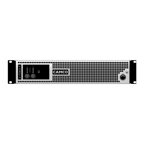
Page 10: D-Power 7 - The Front
D - P O W E R S E R I E S 2.3 D-POWER 7 - The Front 2.4 D-POWER 7 - The Rear 1 Clip LEDs 7 Volume Control Channel A 12 Rating Plate 18 Limiter Switch ®... -
Page 11: 10 2.5 Factory Settings
D-POWER 7 amplifiers are delivered with the following factory settings When mounting or connecting the amp always disconnect it from mains. Only connect the D-POWER 7 amplifier to an appropriate AC cir- cuit and outlet, according to the requirements indicated in the second line on the rating plate. -
Page 12: On/Off Switch P
If a power cut occurs while the amplifier is switched on, it will restart auto- mati cally once the power supply has been restored. All amplifier settings prior to the loss of power will be maintained. 483,00 mm P .11 USER MANUAL D-POWER 7... -
Page 13: Cooling
Pin 1 of the XLRs Removing or taping the mains connector ground is illegal and dangerous. DO NOT REMOVE MAINS CONNECTOR GROUND IT IS ILLEGAL AND DANGEROUS P .12 USER MANUAL D-POWER 7... -
Page 14: Wiring
Two fully independent amplifier channels (normal operating mode). XLR: Pin 1 = Ground (or lifted via 15 Ω resistor) Pin 2 = Hot (inphase) D-POWER 7 Pin 3 = Cold (out of phase) Z ≥ *Z A (L) Always use symmetrical (balanced) shielded cable to connect the amplifier... -
Page 15: Mono Bridge Operation
® outputs. The pin configuration of the SPEAKON connectors is as follows: ® Upper SPEAKON Pin 1+ Channel A signal D-POWER 7 Pin 1- Channel A ground Pin 2+ Channel B signal Pin 2- Channel B ground Z ≥ 2*Z ®... -
Page 16: Controls
Set the volume to zero before turning on the amplifier to prevent the oc- currence of sudden high volume levels which may cause damage to your hearing and/or the speakers. P .15 USER MANUAL D-POWER 7... -
Page 17: Gain Selector
4.1.4 Limiter Switch This switch on the rear of the D-POWER 7 allows the maximum amplification This switch is located at the rear of D-POWER 7. It allows you to set the attainable to be set directly in the input stage. -
Page 18: Indicators
4.2.2 Signal LEDs heavy clipping. The green Signal LED is illuminated when the voltage level at the output reaches approx. 4 V; this corresponds to a power of approx. 4 W over a 4 Ohm resistor. P .17 USER MANUAL D-POWER 7... -
Page 19: Mode Indicators
(bass / Sub bass) and you want to squeeze the absolute maximum out of it, Speaker Protect can be switched off. For all other appli cations (e.g. Full Range) it’s recommended to keep Speaker Protect switched on. P .18 USER MANUAL D-POWER 7... -
Page 20: Dc Protection
4.3.6 DC Servo Mains Failure Detection is always operative. When the mains supply is To prevent DC Offset at the speaker output the D-POWER 7 is fitted with two interrupted for about 2 mains cycles, the amplifier will switch off. When the DC Servos. -
Page 21: Main Smps Protections
(See 5 Troubleshooting). 4.6 Fans The fans mounted in your D-POWER 7 operate permanently, but as long as the temperature remains below 40 °C, they run at their slowest speed and can hardly be heard. The highest detected temperature from either chan- nel controls the speed of the fans. -
Page 22: Filter Cleaning
S E R I E S 4.7 Filter Cleaning The air intake on the front of your D-POWER 7 Amplifier is fitted with a re- To clean or replace the filter just slightly unscrew the fixing screw with the movable filter system. If the filter becomes clogged, the unit will not cool as help of a 3 mm allen key. -
Page 23: On Led Flashing Sequences
5.1 On LED Flashing Sequences When switching on the amp the On LEDs flash twice accompanied by a Examples of LED sequences flash of Clip LEDs. This is normal for the ‘Start’ sequence of the D-POWER 7. LED sequence: Channel 1 :... -
Page 24: Problem: No Sound
• If the On LED sequence indicates “DC, Input Signal Fault”, switch off the Indication: On LEDs lit D-POWER 7 and unplug the amp to disconnect it from the signal source. If Signal LED not lit the On LED shows the same sequence when the D-POWER 7 is switched •Make sure the signal source is operating and try another cable. -
Page 25: Problem: Hiss
Working in stages from the signal source towards the amplifier and check each device in the signal path by reduc- ing its gain or by unplugging it P .24 USER MANUAL D-POWER 7... - Page 26 D - P O W E R S E R I E S D-POWER 7 Output Power, both channels driven 2 x 800 W @ 16 Ω 1 kHz, THD ≤ 1 % @230 V/50 Hz, duration limited by fuse/thermal protection for RL<16 Ω...
- Page 27 483 x 88,9 x 422 mm (19”, 2U) Net Weight 12,4 kg Shipping Dimensions (WxHxD) 615 x 135 x 540 mm (0,045 m3) Shipping Weight 15 kg We reserve the right to make technical alterations without prior notice P .26 USER MANUAL D-POWER 7...
- Page 28 Figure 7.4 Channel separation vs. frequency @ 10 W / 4 Ω (Ch2 => Ch1, Common mode rejection ratio (Ch1, Ch2) Ch1 => Ch2) (Measurements of a typical performance) (Measurements of a typical performance) P .27 USER MANUAL D-POWER 7...
- Page 29 THD+N vs. input voltage @ 1 kHz, 4 Ω (Ch1, Ch2) THD+N vs. frequency (BW 22 kHz), 10 dB below clip, 4 Ω (Ch1, Ch2) (Measurements of a typical performance) (Measurements of a typical performance) P .28 USER MANUAL D-POWER 7...
- Page 30 Impedance / Ω Vrms Figure 7.9 Figure 7.12 CCIF difference frequency method (10,5 kHz and 11,5 kHz) vs. input level D-POWER 7 (Measurements of a typical performance) @ 4 Ω (Ch1, Ch2) (Measurements of a typical performance) -100 100u 200u...
-
Page 31: Summary Of Warranty
8.1 Summary of Warranty 8.4 How to Obtain Warranty Service CAMCO guarantees the D-POWER 7 Amplifier to be free from defective You must notify your dealer/distributor of your need for warranty service. material and/or workmanship for a period of six (6) years from the date of All components must be shipped in the original packaging. - Page 32 Our web site: www.camcoaudio.com provides a complete list of CAMCO Please return the amplifier to the following address or your nearest dealers/distributors. CAMCO appointed distributor. CAMCO Produktions- und Vertriebs-GmbH für Beschallungs- und Beleuchtungsanlagen, Fischpicke 5, D-57482 Wenden, Germany P .31 USER MANUAL D-POWER 7...
-
Page 33: Maintenance Information
Advice on how to carry out these checks can be found in DIN VDE 0702-1 “Safety Checks for Electronic Appliances” . An amplifier that is considered to be unsafe must be labelled accordingly and stored in a safe place to prevent this amplifier being used mistakenly. P .32 USER MANUAL D-POWER 7... - Page 34 D - P O W E R S E R I E S Mailing Address: CAMCO Produktions- und Vertriebs-GmbH für Beschallungs- und Beleuchtungsanlagen Fischpicke 5 D-57482 Wenden Germany Telephone: +49 (0) 2762 408-0 Facsimile: +49 (0) 2762 408-10 Internet: www.camcoaudio.com Email: postmaster@camcoaudio.com...
- Page 35 _ _ _ _ _ _ _ _ _ _ _ _ _ _ _ _ _ _ _ _ _ _ _ _ _ _ _ _ _ _ _ _ _ _ _ _ _ _ _ _ _ _ _ _ _ _ _ _ _ _ _ _ _ _ _ _ _ _ _ _ _ _ P .34 USER MANUAL D-POWER 7...
- Page 36 www.camcoaudio.com...
Need help?
Do you have a question about the D-POWER 7 and is the answer not in the manual?
Questions and answers