Sign In
Upload
Download
Table of Contents
Contents
Add to my manuals
Delete from my manuals
Share
URL of this page:
HTML Link:
Bookmark this page
Add
Manual will be automatically added to "My Manuals"
Print this page
×
Bookmark added
×
Added to my manuals
Manuals
Brands
Camco Manuals
Amplifier
Vortex 6
User manual
Camco Vortex 6 User Manual
Vortex series
Hide thumbs
Also See for Vortex 6
:
User manual
(40 pages)
1
2
3
4
5
6
Table Of Contents
7
8
9
10
11
12
13
14
15
16
17
18
19
20
21
22
23
24
25
26
27
28
29
30
31
32
33
34
35
36
37
38
39
40
41
42
page
of
42
Go
/
42
Contents
Table of Contents
Bookmarks
Table of Contents
Table of Contents
Unpacking
Welcome to CAMCO
The Amplifier
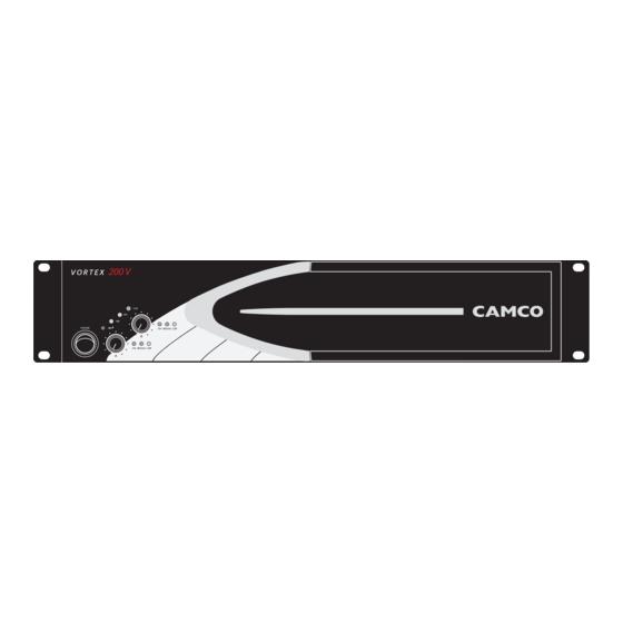
VORTEX - the Front
VORTEX - the Rear
Factory Settings
Mains Supply
On/Off Switch
Mounting
Cooling
Ground Lift
Optional Feature
Mode Indicators
Mode Selector
Wiring
And XLR Connection
Stereo Operation
Parallel-Mono Operation
Mono-Bridge Operation
SPEAKON Connection
Controls
Volume Control
Gain Selector
Gain and Input Sensitivity
Limiter Switch
Indicators
On Leds (Multifunctional)
Power Amp Protection Systems
Clip Limiter
Under Impedance Limiter
SOA Protection
Speaker Protect Limiter
DC Protection
DC Servo
Over Current Protection
Thermal Protection
Signal Leds
Clip Leds (Multifunctional)
Mains Protections
Inrush Current Limitation
Mains over Voltage Detection
Mains Failure Detection
Fuse Protection
Fans
Main SMPS Protections
Over Current Protection
Thermal Protection
Filter Cleaning
CAI Status Indicator
On LED Flashing Sequences
Problem: no Sound
Problem: no Sound or Sound Is too Low
Problem: no Channel Separation
Problem: Distorted Sound
Problem: Hiss
Problem: Squeals and Feedback
Summary of Warranty
Items Excluded from this Warranty
What CAMCO will Do
How to Obtain Warranty Service
Camco's Product Improvement
Maintenance Information
Decomissioning
Advertisement
Quick Links
1
The Amplifier
2
Mono-Bridge Operation
3
On Led Flashing Sequences
Download this manual
Table of
Contents
Previous
Page
Next
Page
1
2
3
4
5
Advertisement
Table of Contents
Need help?
Do you have a question about the Vortex 6 and is the answer not in the manual?
Ask a question
Questions and answers
Related Manuals for Camco Vortex 6
Amplifier Camco 26 dB User Manual
Camco amplifier brochure (40 pages)
Amplifier Camco Vortex Series Owner's Manual
Vortex series (32 pages)
Amplifier Camco VERTOX Series User Manual
Vortex series (44 pages)
Amplifier Camco Vortex Series User Manual
Vortex series (42 pages)
Amplifier Camco Vortex 4 User Manual
Vortex series (42 pages)
Amplifier Camco V8 User Manual
Vortex silver series (36 pages)
Amplifier Camco Vortex 8 Navigation Manual
Silver series (1 page)
Amplifier Camco Vortex 200V User Manual
Vortex series (42 pages)
Amplifier Camco P Series User Manual
Camco amplifier brochure (38 pages)
Amplifier Camco Q-Power 10 User Manual
Camco amplifier brochure (34 pages)
Amplifier Camco iD-Series User Manual
Advanced amplifiers (38 pages)
Amplifier Camco D-POWER 7 User Manual
D-power series (36 pages)
Amplifier Camco Q-POWER 14 User Manual
Power amplifier (42 pages)
Amplifier Camco 38.4 User Manual
Tecton series (38 pages)
Amplifier Camco Q-POWER 10 User Manual
Q-power series (36 pages)
Amplifier Camco Q-Power Series Specifications
Ashly stereo equalizer brochure (2 pages)
This manual is also suitable for:
Vortex 2.6
Vortex 200v
Vortex 4
V
Table of Contents
Print
Rename the bookmark
Delete bookmark?
Delete from my manuals?
Login
Sign In
OR
Sign in with Facebook
Sign in with Google
Upload manual
Upload from disk
Upload from URL


Need help?
Do you have a question about the Vortex 6 and is the answer not in the manual?
Questions and answers