
Related Manuals for Detecto IB Series


Summary of Contents for Detecto IB Series
- Page 1 IB Series Model IBFL500 Assembly Instructions Technical Support: Ph: 866-254-8261 • techsupport@cardet.com Technical Support: Ph: 866-254-8261 • techsupport@cardet.com 0046-M570-O1 Rev A • IBFL500 ASSEMBLY INSTRUCTIONS...
- Page 2 0046-M570-O1 Rev A • IBFL500 ASSEMBLY INSTRUCTIONS...
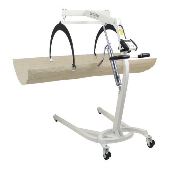
- Page 3 INTRODUCTION Thank you for purchasing our DETECTO™ IB Series Model IBFL500 in-bed scale. It has been manufactured with quality and reliability at our factory in Webb City, MO USA. This scale has been assembled and tested before leaving our factory to insure accuracy and dependability for years to come.
-
Page 4: Packing Checklist
ASSEMBLY INSTRUCTIONS The IB Series Model IBFL500 in-bed scale is shipped disassembled in two (2) separate cartons. Carefully inspect all cartons for damage that may have taken place during shipment. It is the responsibility of the purchaser to file all claims with the shipping company for damages or loss incurred during transit. - Page 5 TWO PEOPLE. PLEASE READ THROUGH THE INSTRUCTIONS CAREFULLY BEFORE STARTING TO ASSEMBLE THE SCALE. Remove the shipping straps and packing material to unpack the IB Series Model IBFL500 in-bed scale. Check the parts against the PACKING CHECKLIST. If any are damaged or missing, please contact our Parts Department at 1-800-641-2045 or by email at parts@cardet.com.
- Page 6 Step 1 – Prepare the Base Assembly 1. With the help of an assistant, remove the Column Assembly from Carton 1. Remove Column Assembly 2. Next, remove the plastic bag and packing from the Base Assembly in Carton 1. Remove Plastic Bag and Packing 3.
- Page 7 Step 2 – Install Column Assembly ¾ 1. Remove the 5/8-11 elastic stop nut and 5/8-11 x 3 1/2” hex head bolt in the top of the base assembly. ¾ 2. Next, then turn the base over (upside down) and remove the 5/8-11 elastic stop nut and 5/8-11 x 3 1/2”...
- Page 8 Step 3 – Install Stretcher Cup 1. Remove the 1/4-20 x 1/2” hex head bolt from the Stretcher Cup mounting bracket. Use the 7/16 wrench if needed. 2. Place the Stretcher Cup on the mounting bracket, align the center hole in the cup with the hole in the mounting bracket and secure with the 1/4-20 x 1/2”...
- Page 9 Step 5 – Install Hydraulic Cylinder 1. Lower the boom assembly and remove the 5/16-18 elastic stop nut and 3/8” split lock washer from the 5/16-18 x 1/2” socket head shoulder bolt in the boom assembly, then slide the bolt out of the boom assembly. IMPORTANT: Note the location of the bolt in the cylinder mounting plate;...
- Page 10 Step 6 – Install Push Handle 1. Remove the (4) 1/4-20 x 1/2” hex head bolts (two on each side) from the column assembly. Use the 7/16” wrench if needed. Remove Push Handle Bolts 2. Place the Push Handle on the column assembly (the opposite direction of the legs) and align the top hole in the handle mounting bracket with the top hole in the column...
- Page 11 Step 7 – Install Stretcher Support Hoops 1. Remove the shipping straps and packing on the boom assembly and load cell tube. Remove Packing & Straps Packing & Straps Removed 2. Remove the outer (2) 1/4-20 x 1/2” socket head screws on the end of load cell tube. Next, loosen the single inner 1/4-20 x 1/2”...
- Page 12 Step 7 – Install Stretcher Support Hoops, Cont. 4. Rotate hoop retainer plate until two outer holes align with the holes in the load cell tube. 5. Remove Loctite® from plastic bag and follow instructions on bag to prepare Loctite®. 6.
- Page 13 Step 8 – Install the Model 750 indicator 1. Remove the indicator from its box and unpack it. Obtain and install six “AA” batteries in the indicator. 2. Route the coiled load cell cable from the boom assembly around the boom and down through the indicator mounting bracket between the bracket supports.
- Page 14 Step 9 – Install the Stretcher 1. Remove the pre-assembled Stretcher and Support Bars from Carton 2 and then unroll the stretcher. Remove Stretcher from box Insure support bars holes are and then unroll the stretcher aligned with stretcher openings 2.
- Page 15 0046-M570-O1 Rev A • IBFL500 ASSEMBLY INSTRUCTIONS...
- Page 16 0046-M570-O1 Rev A • IBFL500 ASSEMBLY INSTRUCTIONS...
Need help?
Do you have a question about the IB Series and is the answer not in the manual?
Questions and answers