
Related Manuals for Nokia 6500 SLIDE RM-240


Summary of Contents for Nokia 6500 SLIDE RM-240
- Page 1 Nokia Customer Care Service Manual RM-240 (Nokia 6500 slide) Mobile Terminal Part No: (Issue 1) COMPANY CONFIDENTIAL Copyright © 2007 Nokia. All rights reserved.
- Page 2 RM-240 Amendment Record Sheet Amendment Record Sheet Amendment No Date Inserted By Comments Original issue 09/2007 J Bryman Finished by G Rudh Page ii COMPANY CONFIDENTIAL Issue 1 Copyright © 2007 Nokia. All rights reserved.
- Page 3 Nokia operates a policy of continuous development. Nokia reserves the right to make changes and improvements to any of the products described in this document without prior notice. Under no circumstances shall Nokia be responsible for any loss of data or income or any special, incidental, consequential or indirect damages howsoever caused.
- Page 4 WCDMA networks and cause problems to 3G cellular phone communication in a wide area. • During testing never activate the GSM or WCDMA transmitter without a proper antenna load, otherwise GSM or WCDMA PA may be damaged. Page iv COMPANY CONFIDENTIAL Issue 1 Copyright © 2007 Nokia. All rights reserved.
- Page 5 Use only approved accessories and batteries. Do not connect incompatible products. CONNECTING TO OTHER DEVICES When connecting to any other device, read its user’s guide for detailed safety instructions. Do not connect incompatible products. Issue 1 COMPANY CONFIDENTIAL Page v Copyright © 2007 Nokia. All rights reserved.
- Page 6 All of the above suggestions apply equally to the product, battery, charger or any accessory. Page vi COMPANY CONFIDENTIAL Issue 1 Copyright © 2007 Nokia. All rights reserved.
- Page 7 RM-240 ESD protection ESD protection Nokia requires that service points have sufficient ESD protection (against static electricity) when servicing the phone. Any product of which the covers are removed must be handled with ESD protection. The SIM card can be replaced without ESD protection if the product is otherwise ready for use.
- Page 8 Batteries' performance is particularly limited in temperatures well below freezing. Do not dispose of batteries in a fire! Dispose of batteries according to local regulations (e.g. recycling). Do not dispose as household waste. Page viii COMPANY CONFIDENTIAL Issue 1 Copyright © 2007 Nokia. All rights reserved.
- Page 9 Our policy is of continuous development; details of all technical modifications will be included with service bulletins. While every endeavour has been made to ensure the accuracy of this document, some errors may exist. If any errors are found by the reader, NOKIA MOBILE PHONES Business Group should be notified in writing/e- mail. Please state: •...
- Page 10 RM-240 Company Policy (This page left intentionally blank.) Page x COMPANY CONFIDENTIAL Issue 1 Copyright © 2007 Nokia. All rights reserved.
- Page 11 Nokia 6500 slide Service Manual Structure 1 General information 2 Service Devices and Service Concepts 3 BB Troubleshooting and Manual Tuning Guide 4 RF troubleshooting 5 System Module Glossary Issue 1 COMPANY CONFIDENTIAL Page xi Copyright © 2007 Nokia. All rights reserved.
- Page 12 RM-240 Nokia 6500 slide Service Manual Structure (This page left intentionally blank.) Page xii COMPANY CONFIDENTIAL Issue 1 Copyright © 2007 Nokia. All rights reserved.
- Page 13 Nokia Customer Care 1 — General information Issue 1 COMPANY CONFIDENTIAL Page 1 –1 Copyright © 2007 Nokia. All rights reserved.
- Page 14 RM-240 General information (This page left intentionally blank.) Page 1 –2 COMPANY CONFIDENTIAL Issue 1 Copyright © 2007 Nokia. All rights reserved.
-
Page 15: Table Of Contents
Table 2 Car accessories ............................1–7 Table 3 Headsets ..............................1–7 Table 4 Data cables ..............................1–7 List of Figures Figure 1 RM-240 (Nokia 6500 slide) product picture ..................1–5 Issue 1 COMPANY CONFIDENTIAL Page 1 –3 Copyright © 2007 Nokia. All rights reserved. - Page 16 RM-240 General information (This page left intentionally blank.) Page 1 –4 COMPANY CONFIDENTIAL Issue 1 Copyright © 2007 Nokia. All rights reserved.
-
Page 17: Product Selection
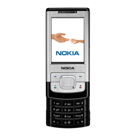
RM-240 General information Product selection RM-240 (Nokia 6500 slide) is a WCDMA/GSM dual mode phone, supporting WCDMA 850/2100 bands and EGSM850/900/1800/1900 bands. Figure 1 RM-240 (Nokia 6500 slide) product picture Phone features Display and keypad features • 2.2” 240x320 pixel, 16M colour display (33.5mm x 44.7mm active area) •... -
Page 18: User Interface And Software Features
Table 1 Battery and chargers Type Name Note: This phone is charged through the smaller charger Nokia standard interface (2.mm plug). The standard 3.5mm standard charger can be used together with the CA-44 charger adapter. Page 1 –6 COMPANY CONFIDENTIAL Issue 1 Copyright ©... -
Page 19: Technical Specifications
NMP Standby time BP-5M 900 mAh Li-ion Up to 6Hours 13.5 Days Note: Variation in operation times will occur depending on SIM card, network settings and usage. Issue 1 COMPANY CONFIDENTIAL Page 1 –7 Copyright © 2007 Nokia. All rights reserved. - Page 20 RM-240 General information (This page left intentionally blank.) Page 1 –8 COMPANY CONFIDENTIAL Issue 1 Copyright © 2007 Nokia. All rights reserved.
- Page 21 Nokia Customer Care 2 — Service Devices and Service Concepts Issue 1 COMPANY CONFIDENTIAL Page 2 –1 Copyright © 2007 Nokia. All rights reserved.
- Page 22 RM-240 Service Devices and Service Concepts (This page left intentionally blank.) Page 2 –2 COMPANY CONFIDENTIAL Issue 1 Copyright © 2007 Nokia. All rights reserved.
-
Page 23: Table Of Contents
2–17 POS (Point of Sale) flash concept ........................2–17 Flash concept with FPS-10..........................2–18 CU-4 flash concept with FPS-10........................2–19 Module jig service concept ..........................2–20 Issue 1 COMPANY CONFIDENTIAL Page 2 –3 Copyright © 2007 Nokia. All rights reserved. - Page 24 Figure 6 Module jig MJ-136 set up (PWB for RM-240 us used) ................ 2–21 Figure 7 RF testing concept with RF coupler ....................2–22 Figure 8 Service concept for RF testing and RF/BB tuning ................2–23 Page 2 –4 COMPANY CONFIDENTIAL Issue 1 Copyright © 2007 Nokia. All rights reserved.
-
Page 25: Service Devices
RJ-180 Rework jig RJ-180 is a jig used for soldering and as a rework jig for the engine module. Issue 1 COMPANY CONFIDENTIAL Page 2 –5 Copyright © 2007 Nokia. All rights reserved. -
Page 26: General Devices
Universal power supply for FPS-10; included in the FPS-10 sales package. ACF-8 Universal power supply ACF-8 universal power supply is used to power FPS-8. ACF-8 has 6V DC and 2.1A output. Page 2 –6 COMPANY CONFIDENTIAL Issue 1 Copyright © 2007 Nokia. All rights reserved. - Page 27 4 Connect an FBUS cable (if necessary). 5 Start Phoenix service software. Note: Phoenix enables CU-4 regulators via USB when it is started. Reconnecting the power supply requires a Phoenix restart. Issue 1 COMPANY CONFIDENTIAL Page 2 –7 Copyright © 2007 Nokia. All rights reserved.
-
Page 28: Fls-4S
FPS-10 sales package includes: • FPS-10 prommer • Power Supply with 5 country specific cords • USB cable Note: FPS-21 is substitute FPS-10 if FPS-10 has not been set Page 2 –8 COMPANY CONFIDENTIAL Issue 1 Copyright © 2007 Nokia. All rights reserved. - Page 29 B2201 component. RJ-196 Rework jig RJ-196 is a rework jig used when servicing the BTHFM (D6000) module. It is used together with rework stencil ST-37. Issue 1 COMPANY CONFIDENTIAL Page 2 –9 Copyright © 2007 Nokia. All rights reserved.
- Page 30 Bluetooth. An ACP-8x charger is needed for BER testing and an AXS-4 cable in case of cordless interface usage testing . Sales package includes: • SB-6 test box • Installation and warranty information Page 2 –10 COMPANY CONFIDENTIAL Issue 1 Copyright © 2007 Nokia. All rights reserved.
- Page 31 SRT-6 Opening tool SRT-6 is used to open phone covers. SS-46 Interface adapter SS-46 acts as an interface adapter between the flash adapter and FPS-10. Issue 1 COMPANY CONFIDENTIAL Page 2 –11 Copyright © 2007 Nokia. All rights reserved.
- Page 32 This stencil is to be used together with RJ-73. ST-37 BTHFM rework stencil ST-37 stencil is used with the RJ-104 rework jig to service the BTHFM (D6000) module. Page 2 –12 COMPANY CONFIDENTIAL Issue 1 Copyright © 2007 Nokia. All rights reserved.
-
Page 33: Cables
The table below gives a short overview of service tools that can be used for testing, error analysis and repair of product RM-240, refer to various concepts. Issue 1 COMPANY CONFIDENTIAL Page 2 –13 Copyright © 2007 Nokia. All rights reserved. -
Page 34: Ca-28Ds
FPS-10 and FPS-11 sales packages. CA-35S Power cable CA-35S is a power cable for connecting, for example, the FPS-10 flash prommer to the Point-Of-Sales (POS) flash adapter. Page 2 –14 COMPANY CONFIDENTIAL Issue 1 Copyright © 2007 Nokia. All rights reserved. -
Page 35: Ca-89Ds
PCS-1 Power cable The PCS-1 power cable (DC) is used with a docking station, a module jig or a control unit to supply a controlled voltage. Issue 1 COMPANY CONFIDENTIAL Page 2 –15 Copyright © 2007 Nokia. All rights reserved. - Page 36 The RF cable is used to connect, for example, a module repair jig to the RF measurement equipment. SMA to N-Connector approximately 610 mm. Attenuation for: • GSM850/900: 0.3+-0.1 dB • GSM1800/1900: 0.5+-0.1 dB • WLAN: 0.6+-0.1dB Page 2 –16 COMPANY CONFIDENTIAL Issue 1 Copyright © 2007 Nokia. All rights reserved.
-
Page 37: Service Concepts
Figure 2 POS flash concept Type Description Product specific tools BP-5C Battery Other tools FLS-5 POS flash dongle PC with Phoenix service software Cables DKE-2 USB connectivity cable Issue 1 COMPANY CONFIDENTIAL Page 2 –17 Copyright © 2007 Nokia. All rights reserved. -
Page 38: Flash Concept With Fps-10
Other devices FPS-10 Flash prommer box PKD-1/PK-1 SW security device SS-46 Interface adapter PC with Phoenix service software Cables XCS-4 Modular cable CA-35S Power cable USB cable Page 2 –18 COMPANY CONFIDENTIAL Issue 1 Copyright © 2007 Nokia. All rights reserved. -
Page 39: Flash Concept With Fps-10
SW security device SS-62 Flash adapter base SX-4 Smart card PC with Phoenix service software Cables PCS-1 Power cable XCS-4 Modular cable Standard USB cable USB cable Issue 1 COMPANY CONFIDENTIAL Page 2 –19 Copyright © 2007 Nokia. All rights reserved. -
Page 40: Module Jig Service Concept
SW security device SX-4 Smart card PC with VPOS and Phoenix service software Measurement equipment Cables PCS-1 DC power cable XCS-4 Modular cable XRF-1 RF cable USB cable Page 2 –20 COMPANY CONFIDENTIAL Issue 1 Copyright © 2007 Nokia. All rights reserved. - Page 41 7 Pass the top flex connector through the jig and connect it on the back side. 8 Put the phone upper part in place on the jig. Issue 1 COMPANY CONFIDENTIAL Page 2 –21 Copyright © 2007 Nokia. All rights reserved.
- Page 42 Flash prommer box PKD-1/PK-1 SW security device SS-62 Flash adapter base Measurement equipment PC with Phoenix service software Cables PCS-1 Power cable XCS-4 Modular cable XRS-6 RF cable Page 2 –22 COMPANY CONFIDENTIAL Issue 1 Copyright © 2007 Nokia. All rights reserved.
- Page 43 Other devices CU-4 Control unit PKD-1/PK-1 SW security device SX-4 Smart card Measurement equipment Smart card reader PC with Phoenix service software Cables DAU-9s MBUS cable Issue 1 COMPANY CONFIDENTIAL Page 2 –23 Copyright © 2007 Nokia. All rights reserved.
- Page 44 RM-240 Service Devices and Service Concepts Type Description PCS-1 DC power cable XRS-6 RF cable GPIB control cable USB cable Page 2 –24 COMPANY CONFIDENTIAL Issue 1 Copyright © 2007 Nokia. All rights reserved.
- Page 45 Nokia Customer Care 3 — BB Troubleshooting and Manual Tuning Guide Issue 1 COMPANY CONFIDENTIAL Page 3 –1 Copyright © 2007 Nokia. All rights reserved.
- Page 46 RM-240 BB Troubleshooting and Manual Tuning Guide (This page left intentionally blank.) Page 3 –2 COMPANY CONFIDENTIAL Issue 1 Copyright © 2007 Nokia. All rights reserved.
- Page 47 Energy management calibration ........................3–51 List of Tables Table 5 Display module troubleshooting cases....................3–21 Table 6 Pixel defects ............................3–22 Table 7 Calibration value limits ......................... 3–51 Issue 1 COMPANY CONFIDENTIAL Page 3 –3 Copyright © 2007 Nokia. All rights reserved.
- Page 48 Figure 12 Differential output waveform of the Ext_in_IHF_out loop measurement when speaker is connected..............................3–38 Figure 13 Single-ended output waveform of the HP_in_Ext_out loop............3–39 Page 3 –4 COMPANY CONFIDENTIAL Issue 1 Copyright © 2007 Nokia. All rights reserved.
-
Page 49: Baseband Self Tests In Phoenix
Always start the troubleshooting procedure by running the Phoenix self tests. If a test fails, please follow the diagram below. Dead or jammed device troubleshooting. If the phone is dead and you cannot perform the self tests, go to Issue 1 COMPANY CONFIDENTIAL Page 3 –5 Copyright © 2007 Nokia. All rights reserved. - Page 50 RM-240 BB Troubleshooting and Manual Tuning Guide Troubleshooting flow Page 3 –6 COMPANY CONFIDENTIAL Issue 1 Copyright © 2007 Nokia. All rights reserved.
-
Page 51: Power And Charging Troubleshooting
RM-240 BB Troubleshooting and Manual Tuning Guide Power and charging troubleshooting Dead or jammed device troubleshooting Troubleshooting flow Issue 1 COMPANY CONFIDENTIAL Page 3 –7 Copyright © 2007 Nokia. All rights reserved. - Page 52 RM-240 BB Troubleshooting and Manual Tuning Guide Troubleshooting flow Page 3 –8 COMPANY CONFIDENTIAL Issue 1 Copyright © 2007 Nokia. All rights reserved.
-
Page 53: General Power Checking
VLEDOUT TPS61061/ 14.5 LCD Backlight Disabled in N2301 sleep VLED TPS75105/ Keyboard Disabled in N2401 backlight sleep VTVO TK63115B-G/ TV out Disabled in N2411 sleep Issue 1 COMPANY CONFIDENTIAL Page 3 –9 Copyright © 2007 Nokia. All rights reserved. -
Page 54: Charging Troubleshooting
RM-240 BB Troubleshooting and Manual Tuning Guide Charging troubleshooting Troubleshooting flow Page 3 –10 COMPANY CONFIDENTIAL Issue 1 Copyright © 2007 Nokia. All rights reserved. -
Page 55: Interface Troubleshooting
RM-240 BB Troubleshooting and Manual Tuning Guide Interface troubleshooting Flash programming fault troubleshooting Part 1 Issue 1 COMPANY CONFIDENTIAL Page 3 –11 Copyright © 2007 Nokia. All rights reserved. - Page 56 RM-240 BB Troubleshooting and Manual Tuning Guide Part 2 Figure 9 Flashing pic 1. Take single trig measurement for the rise of the BSI signal. Page 3 –12 COMPANY CONFIDENTIAL Issue 1 Copyright © 2007 Nokia. All rights reserved.
- Page 57 RM-240 BB Troubleshooting and Manual Tuning Guide Figure 10 Flashing pic 2. Take single trig measurement for the rise of the BSI signal. Issue 1 COMPANY CONFIDENTIAL Page 3 –13 Copyright © 2007 Nokia. All rights reserved.
-
Page 58: Combo Memory Troubleshooting
RM-240 BB Troubleshooting and Manual Tuning Guide Combo memory troubleshooting Troubleshooting flow Page 3 –14 COMPANY CONFIDENTIAL Issue 1 Copyright © 2007 Nokia. All rights reserved. -
Page 59: Sd Card Troubleshooting
RM-240 BB Troubleshooting and Manual Tuning Guide SD card troubleshooting Troubleshooting flow Issue 1 COMPANY CONFIDENTIAL Page 3 –15 Copyright © 2007 Nokia. All rights reserved. -
Page 60: Usb Interface Troubleshooting
RM-240 BB Troubleshooting and Manual Tuning Guide USB interface troubleshooting Troubleshooting flow Page 3 –16 COMPANY CONFIDENTIAL Issue 1 Copyright © 2007 Nokia. All rights reserved. -
Page 61: Sim Card Troubleshooting
RM-240 BB Troubleshooting and Manual Tuning Guide SIM card troubleshooting Troubleshooting flow Issue 1 COMPANY CONFIDENTIAL Page 3 –17 Copyright © 2007 Nokia. All rights reserved. -
Page 62: Tv Out Troubleshooting
RM-240 BB Troubleshooting and Manual Tuning Guide TV out troubleshooting Troubleshooting flow Page 3 –18 COMPANY CONFIDENTIAL Issue 1 Copyright © 2007 Nokia. All rights reserved. -
Page 63: User Interface Troubleshooting
• Malfunction of several keys at the same time; this happens when one or more rows or columns in the key matrix are failing (shortcut or open connection). If the failure mode is not clear, start with the Keyboard test in Phoenix. Numeric keypad troubleshooting Issue 1 COMPANY CONFIDENTIAL Page 3 –19 Copyright © 2007 Nokia. All rights reserved. - Page 64 RM-240 BB Troubleshooting and Manual Tuning Guide Top keypad troubleshooting Page 3 –20 COMPANY CONFIDENTIAL Issue 1 Copyright © 2007 Nokia. All rights reserved.
-
Page 65: Display Module Troubleshooting
If a part of the image is missing, change the display module. If the image is otherwise corrupted, follow the appropriate troubleshooting diagram. Issue 1 COMPANY CONFIDENTIAL Page 3 –21 Copyright © 2007 Nokia. All rights reserved. -
Page 66: Blank Display Troubleshooting
Blank display troubleshooting Context The phone is in normal mode and there is no image on the display. Display back light could be on in some cases. Page 3 –22 COMPANY CONFIDENTIAL Issue 1 Copyright © 2007 Nokia. All rights reserved. -
Page 67: Faulty Image Troubleshooting
The image on the display is corrupted or part of the image is missing. If a part of the image is missing, change the display module. Otherwise, follow the flowchart below. Issue 1 COMPANY CONFIDENTIAL Page 3 –23 Copyright © 2007 Nokia. All rights reserved. - Page 68 RM-240 BB Troubleshooting and Manual Tuning Guide Troubleshooting flow Page 3 –24 COMPANY CONFIDENTIAL Issue 1 Copyright © 2007 Nokia. All rights reserved.
-
Page 69: Display On But No Image Troubleshooting
BB Troubleshooting and Manual Tuning Guide Display on but no image troubleshooting Context The phone is on, display active and blank, but no image. Troubleshooting flow Issue 1 COMPANY CONFIDENTIAL Page 3 –25 Copyright © 2007 Nokia. All rights reserved. -
Page 70: Display Backlight Troubleshooting
RM-240 BB Troubleshooting and Manual Tuning Guide Display backlight troubleshooting Troubleshooting flow Page 3 –26 COMPANY CONFIDENTIAL Issue 1 Copyright © 2007 Nokia. All rights reserved. -
Page 71: Hall Sensor Troubleshooting
30mm. Replace faulty hall sensors. 3 If the fault remains - replace the PWB. 4 If the problem remains - check the magnet. Issue 1 COMPANY CONFIDENTIAL Page 3 –27 Copyright © 2007 Nokia. All rights reserved. -
Page 72: Camera Module Troubleshooting
Bad conditions often cause bad pictures. Therefore, the camera operation has to be checked in constant conditions or by using a second, known-to-be-good Nokia device as reference. Image quality is hard to measure quantitatively, and the difference between a good and a bad picture can be small. Some training or experience may be needed to detect what is actually wrong. -
Page 73: Camera Hardware Troubleshooting
• The image may be blurred, though it does not show in the viewfinder • Analyse the picture from your PC monitor, full colour setting is recommended • If possible, compare with a picture of the same motive taken with a similar Nokia device Camera hardware troubleshooting... -
Page 74: Camera Hardware Troubleshooting
RM-240 BB Troubleshooting and Manual Tuning Guide Camera hardware troubleshooting Troubleshooting flow Page 3 –30 COMPANY CONFIDENTIAL Issue 1 Copyright © 2007 Nokia. All rights reserved. -
Page 75: Small (Front) Camera Troubleshooting
Do not evaluate the picture on the receiving phone. • The center of the picture is sharper than the edges • If possible, compare with the picture on another Nokia device in a videocall, and of the same motive. Issue 1 COMPANY CONFIDENTIAL Page 3 –31... -
Page 76: Small (Front) Camera Bad Image Quality Troubleshooting
RM-240 BB Troubleshooting and Manual Tuning Guide Small (front) camera bad image quality troubleshooting Troubleshooting flow Page 3 –32 COMPANY CONFIDENTIAL Issue 1 Copyright © 2007 Nokia. All rights reserved. -
Page 77: Small (Front) Camera Troubleshooting
RM-240 BB Troubleshooting and Manual Tuning Guide Small (front) camera troubleshooting Troubleshooting flow Issue 1 COMPANY CONFIDENTIAL Page 3 –33 Copyright © 2007 Nokia. All rights reserved. -
Page 78: Small (Front) Camera Hardware Troubleshooting
RM-240 BB Troubleshooting and Manual Tuning Guide Small (front) camera hardware troubleshooting Troubleshooting flow Page 3 –34 COMPANY CONFIDENTIAL Issue 1 Copyright © 2007 Nokia. All rights reserved. -
Page 79: Led Camera Flash Troubleshooting
2kHz. The input signal for each loop test can be either single-ended or differential. Required equipment The following equipment is needed for the tests: Issue 1 COMPANY CONFIDENTIAL Page 3 –35 Copyright © 2007 Nokia. All rights reserved. - Page 80 HSEAR R N and GND HSEAR P, HSEAR N and GND XMICN and HSEAR R P, HSEAR R N and GND HSEAR P, HSEAR N and GND Page 3 –36 COMPANY CONFIDENTIAL Issue 1 Copyright © 2007 Nokia. All rights reserved.
- Page 81 (OUT/GND) HSEAR R N and GND HSEAR P, HSEAR N and GND HSEAR R P, HSEAR R N and GND HSEAR P, HSEAR N and GND Issue 1 COMPANY CONFIDENTIAL Page 3 –37 Copyright © 2007 Nokia. All rights reserved.
- Page 82 If a special low-pass filter designed for measuring digital amplifiers is unavailable, the measurement must be performed with a current probe and the input signal frequency must be 2kHz. Figure 12 Differential output waveform of the Ext_in_IHF_out loop measurement when speaker is connected. Page 3 –38 COMPANY CONFIDENTIAL Issue 1 Copyright © 2007 Nokia. All rights reserved.
- Page 83 RM-240 BB Troubleshooting and Manual Tuning Guide Figure 13 Single-ended output waveform of the HP_in_Ext_out loop. Issue 1 COMPANY CONFIDENTIAL Page 3 –39 Copyright © 2007 Nokia. All rights reserved.
-
Page 84: Internal Earpiece Troubleshooting
RM-240 BB Troubleshooting and Manual Tuning Guide Internal earpiece troubleshooting Troubleshooting flow Page 3 –40 COMPANY CONFIDENTIAL Issue 1 Copyright © 2007 Nokia. All rights reserved. -
Page 85: Internal Microphone Troubleshooting
RM-240 BB Troubleshooting and Manual Tuning Guide Internal microphone troubleshooting Troubleshooting flow Issue 1 COMPANY CONFIDENTIAL Page 3 –41 Copyright © 2007 Nokia. All rights reserved. -
Page 86: Internal Handsfree (Ihf) Troubleshooting
RM-240 BB Troubleshooting and Manual Tuning Guide Internal handsfree (IHF) troubleshooting Troubleshooting flow Page 3 –42 COMPANY CONFIDENTIAL Issue 1 Copyright © 2007 Nokia. All rights reserved. -
Page 87: External Earpiece Troubleshooting
RM-240 BB Troubleshooting and Manual Tuning Guide External earpiece troubleshooting Troubleshooting flow Issue 1 COMPANY CONFIDENTIAL Page 3 –43 Copyright © 2007 Nokia. All rights reserved. -
Page 88: External Microphone Troubleshooting
RM-240 BB Troubleshooting and Manual Tuning Guide External microphone troubleshooting Troubleshooting flow Page 3 –44 COMPANY CONFIDENTIAL Issue 1 Copyright © 2007 Nokia. All rights reserved. -
Page 89: Vibra Troubleshooting
Note: USB flashing does not work for a dead BB5 phone. • Create a request file. • Send the file to Nokia by e-mail. Use the following addresses depending on your location: • APAC: sydney.service@nokia.com • CHINA: repair.ams@nokia.com • E&A: salo.repair@nokia.com •... - Page 90 Wait for the phone type designator (e.g. “RM-1” ) to be displayed in the status bar. Phoenix reads the product data as shown in the following iv Go to Flashing→SW Update and wait until picture. Page 3 –46 COMPANY CONFIDENTIAL Issue 1 Copyright © 2007 Nokia. All rights reserved.
- Page 91 Flash Type must be set to Phone as Manufactured. To continue, click Start. Progress bars and messages on the screen show actions during phone programming, please wait. Issue 1 COMPANY CONFIDENTIAL Page 3 –47 Copyright © 2007 Nokia. All rights reserved.
- Page 92 Phoenix , choose File→Scan Product . To connect the phone with ii Choose Tools→Certificate Restore . iii To choose a location for the request file, click Browse. Page 3 –48 COMPANY CONFIDENTIAL Issue 1 Copyright © 2007 Nokia. All rights reserved.
- Page 93 Request file, click Start. To create the vi When the file for certificate restore has been created, send it to Nokia as an e-mail attachment. 3. Restore certificate. For this procedure, you must supply +12 V to CU-4 from an external power supply.
- Page 94 To write the file to phone, click Start. Next actions Phoenix tuning functions. After a successful rewrite, you must retune the phone completely by using Important: Perform all tunings: RF, BB, and UI. Page 3 –50 COMPANY CONFIDENTIAL Issue 1 Copyright © 2007 Nokia. All rights reserved.
-
Page 95: Energy Management Calibration
Write and/or repeat the procedure again. Energy Management Calibration window. 10. To end the procedure, close the Issue 1 COMPANY CONFIDENTIAL Page 3 –51 Copyright © 2007 Nokia. All rights reserved. - Page 96 RM-240 BB Troubleshooting and Manual Tuning Guide (This page left intentionally blank.) Page 3 –52 COMPANY CONFIDENTIAL Issue 1 Copyright © 2007 Nokia. All rights reserved.
- Page 97 Nokia Customer Care 4 — RF troubleshooting Issue 1 COMPANY CONFIDENTIAL Page 4 –1 Copyright © 2007 Nokia. All rights reserved.
- Page 98 RM-240 RF troubleshooting (This page left intentionally blank.) Page 4 –2 COMPANY CONFIDENTIAL Issue 1 Copyright © 2007 Nokia. All rights reserved.
- Page 99 Figure 15 General voltage checking test points (main board, top side) ............4–11 Figure 16 RX Control window with example settings ..................4–13 Figure 17 Typical readings ..........................4–16 Figure 18 Troubleshooting diagram: Bluetooth ....................4–18 Issue 1 COMPANY CONFIDENTIAL Page 4 –3 Copyright © 2007 Nokia. All rights reserved.
- Page 100 RM-240 RF troubleshooting (This page left intentionally blank.) Page 4 –4 COMPANY CONFIDENTIAL Issue 1 Copyright © 2007 Nokia. All rights reserved.
-
Page 101: Rf Self Tests In Phoenix
RF self tests in Phoenix Context Always start the troubleshooting procedure by running the Phoenix self tests. If a test fails, please follow the diagram below. Troubleshooting flow Issue 1 COMPANY CONFIDENTIAL Page 4 –5 Copyright © 2007 Nokia. All rights reserved. -
Page 102: General Rf Troubleshooting
Please refer to the list of Note: If the RF shieldning can is removed (for measurement or repair), it must always be replaced with a new one. RF key components Page 4 –6 COMPANY CONFIDENTIAL Issue 1 Copyright © 2007 Nokia. All rights reserved. -
Page 103: Non-Replaceable Rf Components
RM-240 RF troubleshooting Non-replaceable RF components The following RF components cannot be replaced because of their location on the PWB: Issue 1 COMPANY CONFIDENTIAL Page 4 –7 Copyright © 2007 Nokia. All rights reserved. -
Page 104: Auto Tuning For Bb5.0
• Product specific module jig • Cables: XRF-1 (RF cable), USB cable, GBIP cable and DAU-9S or one device including all. • Signal analyser (TX), signal generator (RX) and RF-splitter Page 4 –8 COMPANY CONFIDENTIAL Issue 1 Copyright © 2007 Nokia. All rights reserved. -
Page 105: General Voltage Checking
Vbat at WCDMA PA C7547 3.9 V Supply input to DC/DC conv L7591 3.9 V * With these settings, the result should be 1.3 V. Issue 1 COMPANY CONFIDENTIAL Page 4 –9 Copyright © 2007 Nokia. All rights reserved. - Page 106 RM-240 RF troubleshooting Page 4 –10 COMPANY CONFIDENTIAL Issue 1 Copyright © 2007 Nokia. All rights reserved.
- Page 107 RM-240 RF troubleshooting Figure 15 General voltage checking test points (main board, top side) Issue 1 COMPANY CONFIDENTIAL Page 4 –11 Copyright © 2007 Nokia. All rights reserved.
-
Page 108: Receiver Troubleshooting
Q branch and I Branch . In each case the reading should be 3 dB below Now select the measuring mode to the signal generator level. Page 4 –12 COMPANY CONFIDENTIAL Issue 1 Copyright © 2007 Nokia. All rights reserved. -
Page 109: Wcdma Rx Chain Activation For Manual Measurement/Wcdma Rssi Measurement
Clicking Stop also disables TX control if it was active. 4. From the Phoenix testing menu, select WCDMA→RX Power measurement 5. In the RX Power measurement window, select: • Mode: RSSI Issue 1 COMPANY CONFIDENTIAL Page 4 –13 Copyright © 2007 Nokia. All rights reserved. -
Page 110: Transmitter Troubleshooting
GSM transmitter troubleshooting Steps 1. Set the phone to local mode. 2. Activate RF controls in Phoenix (Testing→GSM→Rf Controls ). Make settings as shown in the picture: Page 4 –14 COMPANY CONFIDENTIAL Issue 1 Copyright © 2007 Nokia. All rights reserved. - Page 111 RM-240 RF troubleshooting 3. Check the basic TX parameters (i.e. power, phase error, modulation and switching spectrum), using a communication analyser (for example CMU200). Issue 1 COMPANY CONFIDENTIAL Page 4 –15 Copyright © 2007 Nokia. All rights reserved.
- Page 112 RM-240 RF troubleshooting Figure 17 Typical readings 4. Change power level (RF controls) and make sure the power reading follows accordingly. Page 4 –16 COMPANY CONFIDENTIAL Issue 1 Copyright © 2007 Nokia. All rights reserved.
-
Page 113: Wcdma Transmitter Troubleshooting
5. Check the basic TX parameters (i.e. power and EVM) using a communication analyser (eg. CMU200). 6. To repeat the test for other bands, select the correct band in the TX control and repeat the measurements. Issue 1 COMPANY CONFIDENTIAL Page 4 –17 Copyright © 2007 Nokia. All rights reserved. -
Page 114: Bluetooth And Fm Radio Troubleshooting
RM-240 RF troubleshooting Bluetooth and FM radio troubleshooting Bluetooth troubleshooting Troubleshooting flow Figure 18 Troubleshooting diagram: Bluetooth Page 4 –18 COMPANY CONFIDENTIAL Issue 1 Copyright © 2007 Nokia. All rights reserved. -
Page 115: Fm Radio Troubleshooting
RM-240 RF troubleshooting FM radio troubleshooting Troubleshooting flow Issue 1 COMPANY CONFIDENTIAL Page 4 –19 Copyright © 2007 Nokia. All rights reserved. - Page 116 RM-240 RF troubleshooting (This page left intentionally blank.) Page 4 –20 COMPANY CONFIDENTIAL Issue 1 Copyright © 2007 Nokia. All rights reserved.
- Page 117 Nokia Customer Care 5 — System Module Issue 1 COMPANY CONFIDENTIAL Page 5 –1 Copyright © 2007 Nokia. All rights reserved.
- Page 118 RM-240 System Module (This page left intentionally blank.) Page 5 –2 COMPANY CONFIDENTIAL Issue 1 Copyright © 2007 Nokia. All rights reserved.
- Page 119 ............................5–15 Figure 24 Camera block diagram........................5–16 Figure 25 Audio block diagram.......................... 5–18 Figure 26 Bluetooth interface ..........................5–20 Figure 27 FM interface ............................5–21 Issue 1 COMPANY CONFIDENTIAL Page 5 –3 Copyright © 2007 Nokia. All rights reserved.
- Page 120 RM-240 System Module (This page left intentionally blank.) Page 5 –4 COMPANY CONFIDENTIAL Issue 1 Copyright © 2007 Nokia. All rights reserved.
-
Page 121: Introduction
RTC back-up battery 311 G2200 FM radio BTHFMRDS2.0 module D6000 Bluetooth BTHFMRDS2.0 module D6000 Slide switch Hall IC switch/position sensor N2421, N2422 Battery BP-5M Battery connector Blade interface X2070 Issue 1 COMPANY CONFIDENTIAL Page 5 –5 Copyright © 2007 Nokia. All rights reserved. - Page 122 D2430 Earpiece B2170 Secondary camera N3550 Microphone Knopfler, digital interface B2102 µSD card connector X4800 AV connector 2.5 mm X2001 µUSB connector X2002 Key component placement Page 5 –6 COMPANY CONFIDENTIAL Issue 1 Copyright © 2007 Nokia. All rights reserved.
- Page 123 RM-240 System Module Issue 1 COMPANY CONFIDENTIAL Page 5 –7 Copyright © 2007 Nokia. All rights reserved.
- Page 124 RM-240 System Module System module block diagram Page 5 –8 COMPANY CONFIDENTIAL Issue 1 Copyright © 2007 Nokia. All rights reserved.
- Page 125 RM-240 System Module Board and module connections Issue 1 COMPANY CONFIDENTIAL Page 5 –9 Copyright © 2007 Nokia. All rights reserved.
-
Page 126: Energy Management
The BSI line is used to recognize the battery capacity by a battery internal pull down resistor. Figure 20 Blade battery connector Charging This phone is charged through the smaller Nokia standard interface (2.0 mm plug). The wider standard charger (3.5 mm) can be used together with the CA-44 charger adapter. Page 5 –10... -
Page 127: Normal And Extreme Voltages
When the end call key is pressed, the system boots up (if an adequate battery voltage is present). Issue 1 COMPANY CONFIDENTIAL Page 5 –11 Copyright © 2007 Nokia. All rights reserved. -
Page 128: Modes Of Operation
CLK600. The clock source is an internal RC oscillator in EM ASIC N2300 (during the power-up sequence) or RAPIDO SMPS Clk. Sys Clk. The Sys Clock is used for the camera hardware accelerator (HWA, N3400). Page 5 –12 COMPANY CONFIDENTIAL Issue 1 Copyright © 2007 Nokia. All rights reserved. -
Page 129: Usb, Sim, Μsd, Tv Out
Depending on the position of the switch (N2002), compressed video signal is feed to pin 3 or audio input from external microphone is feed to the phone. Note: Only use an approved cable for connecting to the AV connector (CA-92U). Issue 1 COMPANY CONFIDENTIAL Page 5 –13 Copyright © 2007 Nokia. All rights reserved. -
Page 130: Sim Interface
The SIM interface consists of an internal interface between RAP and EM ASIC (N2200), and of an external interface between N2200 and SIM contacts. The SIM IF is shown in the following figure: Page 5 –14 COMPANY CONFIDENTIAL Issue 1 Copyright © 2007 Nokia. All rights reserved. -
Page 131: Μsd Card Interface
The camera is supported by a hardware accelerator (HWA - N3400) which also handles the camera flash function (double LED flash diodes). The secondary camera is used for video calling and is basically handled in a similar way to the main camera. Issue 1 COMPANY CONFIDENTIAL Page 5 –15 Copyright © 2007 Nokia. All rights reserved. -
Page 132: User Interface
The LCD module does not require any tuning in service. Keyboard and other keys Table 10 Key signal matrix GENIO KEYB_CMT8 KEYB_CMT9 KEYB_CMT1 KEYB_CMT1 KEYB_CMT1 (COL0) (COL1) 0 (COL2) 1 (COL3) 2 (COL4) Page 5 –16 COMPANY CONFIDENTIAL Issue 1 Copyright © 2007 Nokia. All rights reserved. -
Page 133: Backlight And Illumination
1.8V when not active. This arrangement makes the phone able to detect - closed and open position. The two hall sensors are overlapping each other to cover the entire sliding range. Issue 1 COMPANY CONFIDENTIAL Page 5 –17 Copyright © 2007 Nokia. All rights reserved. -
Page 134: Audio Concept
All external audio accessories are connected to the specific audio connector. Figure 25 Audio block diagram Internal audio The internal audio components are used in these modes: Page 5 –18 COMPANY CONFIDENTIAL Issue 1 Copyright © 2007 Nokia. All rights reserved. -
Page 135: Audio
HS_ GND Ground) HS_MIC/ Input/Output Microphone input Video output depending on HS_COMP_VIDEO switch N2002 HS_EAR_R Output Audio out HS_EAR_L Output Audio out PLUG_DET Input Plug detection Issue 1 COMPANY CONFIDENTIAL Page 5 –19 Copyright © 2007 Nokia. All rights reserved. -
Page 136: Rf Description
FM radio The FM radio is physically integrated with the Bluetooth into one single module. From a functional point of view they, however, have nothing in common. Page 5 –20 COMPANY CONFIDENTIAL Issue 1 Copyright © 2007 Nokia. All rights reserved. -
Page 137: Receiver (Rx)
The receiver functions are implemented in the RF ASIC. Signals with different frequencies take different paths, therefore being handled by different components. The principle of GSM and WCDMA is the same. Issue 1 COMPANY CONFIDENTIAL Page 5 –21 Copyright © 2007 Nokia. All rights reserved. -
Page 138: Transmitter (Tx)
Even though the GSM and WCDMA signals are sent via different components, the principles of the transmission is the same. Technical specifications Main RF characteristics for GSM and WCDMA band phones Parameter Unit Cellular system EGSM850/900/1800/1900 + WCDMA band I/V Page 5 –22 COMPANY CONFIDENTIAL Issue 1 Copyright © 2007 Nokia. All rights reserved. - Page 139 WCDMA band V: 108 Channel spacing GSM 200 KHz WCDMA 4.8 MHz Number of Tx power levels GSM850: 15 GSM900: 15 GSM1800: 16 GSM1900: 16 WCDMA: 75 Issue 1 COMPANY CONFIDENTIAL Page 5 –23 Copyright © 2007 Nokia. All rights reserved.
-
Page 140: Environmental Conditions
Condensed or dripping water may cause intermittent malfunctions. Protection against dripping water has to be implemented in (enclosure) mechanics. Continuous dampness will cause permanent damage to the module. Page 5 –24 COMPANY CONFIDENTIAL Issue 1 Copyright © 2007 Nokia. All rights reserved. - Page 141 Nokia Customer Care Glossary Issue 1 COMPANY CONFIDENTIAL Page Glossary–1 Copyright © 2007 Nokia. All rights reserved.
- Page 142 RM-240 Glossary (This page left intentionally blank.) Page Glossary–2 COMPANY CONFIDENTIAL Issue 1 Copyright © 2007 Nokia. All rights reserved.
- Page 143 D/A-converter Digital-to-analouge converter Digital-to-analouge converter Digital Battery Interface DBus DSP controlled serial bus connected between UPP_WD2 and Helgo DCT-4 Digital Core Technology Direct memory access Data Package Issue 1 COMPANY CONFIDENTIAL Page Glossary–3 Copyright © 2007 Nokia. All rights reserved.
- Page 144 Integrated hands free IMEI International Mobile Equipment Identity Infrared IrDA Infrared Data Associasion Intelligent software architecture JPEG/JPG Joint Photographic Experts Group Liquid Crystal Display Low Drop Out Page Glossary–4 COMPANY CONFIDENTIAL Issue 1 Copyright © 2007 Nokia. All rights reserved.
- Page 145 Serial control Bus For RF Right Soft Key RS-MMC Reduced size Multi Media Card RSSI Receiving signal strength indicator Reset Switch Real Time Clock (provides date and time) Issue 1 COMPANY CONFIDENTIAL Page Glossary–5 Copyright © 2007 Nokia. All rights reserved.
- Page 146 Peak-to-peak voltage VSIM SIM voltage Wireless application protocol Watchdog XHTML Extensible hypertext markup language Zocus Current sensor, (used to monitor the current flow to and from the battery) Page Glossary–6 COMPANY CONFIDENTIAL Issue 1 Copyright © 2007 Nokia. All rights reserved.
Need help?
Do you have a question about the 6500 SLIDE RM-240 and is the answer not in the manual?
Questions and answers