Toro 38597 Operator's Manual
Hide thumbs
Also See for 38597:
- Operator's manual (28 pages) ,
- Operator's manual (32 pages) ,
- Operator's manual (29 pages)
Table of Contents
Advertisement
Quick Links
Power Max
Model No. 38597—Serial No. 290000001 and Up
Introduction
Read this information carefully to learn how to operate
and maintain your product properly and to avoid injury
and product damage. You are responsible for operating
the product properly and safely.
You may contact Toro directly at www.Toro.com for
product and accessory information, help finding a
dealer, or to register your product.
Whenever you need service, genuine Toro parts, or
additional information, contact an Authorized Service
Dealer or Toro Customer Service and have the model
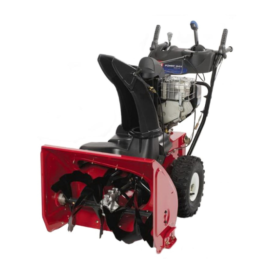
and serial numbers of your product ready. Figure 1
identifies the location of the model and serial numbers
on the product. Write the numbers in the space
provided.
Figure 1
1. Model and serial number location
Model No.
Serial No.
This manual identifies potential hazards and has
safety messages identified by the safety alert symbol
(Figure 2), which signals a hazard that may cause serious
© 2008—The Toro® Company
8111 Lyndale Avenue South
Bloomington, MN 55420
®
826 O Snowthrower
injury or death if you do not follow the recommended
precautions.
1. Safety alert symbol
This manual uses 2 words to highlight information.
Important calls attention to special mechanical
information and Note emphasizes general information
worthy of special attention.
Replacement Engine Owner's Manuals may be
ordered through the engine manufacturer.
Register at www.Toro.com.
Form No. 3360-748 Rev A
Operator's Manual
Figure 2
Original Instructions (EN)
Printed in the USA
All Rights Reserved
Advertisement
Table of Contents


Need help?
Do you have a question about the 38597 and is the answer not in the manual?
Questions and answers