Table of Contents
Advertisement
Quick Links
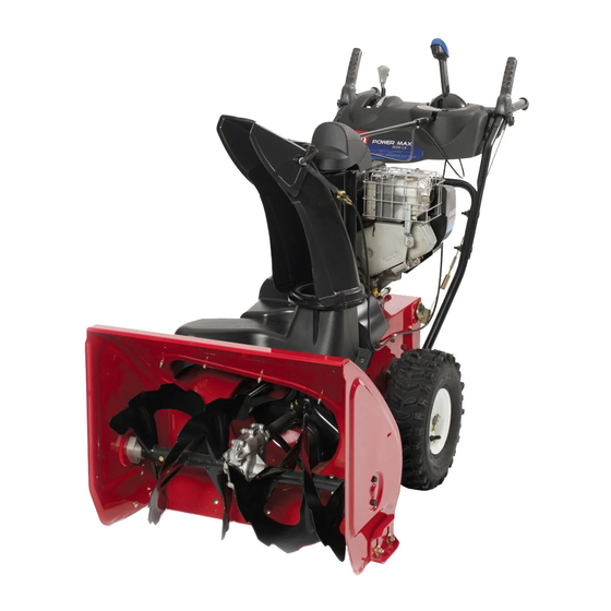
Power Max
Model No. 38657—Serial No. 290000001 and Up
Introduction
Read this information carefully to learn how to operate
and maintain your product properly and to avoid injury
and product damage. You are responsible for operating
the product properly and safely.
You may contact Toro directly at www.Toro.com for
product and accessory information, help finding a
dealer, or to register your product.
Whenever you need service, genuine Toro parts, or
additional information, contact an Authorized Service
Dealer or Toro Customer Service and have the model
and serial numbers of your product ready. Figure 1
identifies the location of the model and serial numbers
on the product. Write the numbers in the space
provided.
Figure 1
1. Model and serial number location
Model No.
Serial No.
This manual identifies potential hazards and has
safety messages identified by the safety alert symbol
(Figure 2), which signals a hazard that may cause serious
© 2008—The Toro® Company
8111 Lyndale Avenue South
Bloomington, MN 55420
®
1128 OXE Snowthrower
injury or death if you do not follow the recommended
precautions.
1. Safety alert symbol
This manual uses 2 words to highlight information.
Important calls attention to special mechanical
information and Note emphasizes general information
worthy of special attention.
Replacement Engine Owner's Manuals may be
ordered through the engine manufacturer.
Register at www.Toro.com.
Form No. 3360-759 Rev A
Operator's Manual
Figure 2
Original Instructions (EN)
Printed in the USA
All Rights Reserved
Advertisement
Table of Contents

Related Manuals for Toro 38657


Summary of Contents for Toro 38657
- Page 1 Important calls attention to special mechanical additional information, contact an Authorized Service information and Note emphasizes general information Dealer or Toro Customer Service and have the model worthy of special attention. and serial numbers of your product ready. Figure 1 identifies the location of the model and serial numbers Replacement Engine Owner’s Manuals may be...
- Page 2 Safety Before Operating Caution: Improper use may result in loss of fingers, hands, or feet. Read and understand the contents of this manual before operating the snowthrower There is a high-speed Become familiar with all controls and know impeller close to the how to stop the engine quickly opening.
-
Page 3: Maintenance And Storage
• Do not clear snow across the face of slopes. Exercise The following list contains safety information specific extreme caution when changing direction on slopes. to Toro products or other safety information that you Do not attempt to clear steep slopes. must know. -
Page 4: Sound Pressure
• If a shield, safety device, or decal is damaged, • Purchase only genuine Toro replacement parts and accessories. illegible, or lost, repair or replace it before beginning operation. Also, tighten any loose fasteners. - Page 5 112-6625 Reorder part no. 112-6629 1. Cutting/dismemberment hazard, impeller—do not place your hand in the chute; stop the engine before leaving the operator’s position, use the tool to clear the chute. 112-6627 1. Left turn control 3. Warning—read the 5. Cutting/dismemberment 7.
- Page 6 Briggs Part No. 276925 Briggs Part No. 277566 1. Warning—read the 3. Warning—toxic gas 1. When starting a cold 2. When starting a warm Operator’s Manual. inhalation hazard. engine, close the choke engine, open the choke 2. Warning—fire hazard. 4. Warning—hot and press the primer two and do not press the surface/burn hazard.
-
Page 7: Installing The Upper Handle
1. Installing the Upper Handle 2. Installing the Wheel Clutch Cable Ends Handle bolts Curved washers Procedure Locknuts 1. Unwrap the cable ends from the lower handle (Figure 5). Procedure Note: Do not remove the rubber band on the cables until you have installed the upper handle. - Page 8 Important: Ensure that the curved side of the cable clamp is against the handle and that the cable is routed below the clamp bolt. The cable must be in a straight line from the cable clamp to the point where it attaches to the wheel clutch lever.
- Page 9 6. Lift up on the speed control rod and insert the trunnion into the hole in the speed selector lever (Figure 11). Note: If the trunnion does not fit into the hole when you lift up on the speed control rod, rotate the trunnion upward or downward on the speed control rod until it fits.
-
Page 10: Filling The Engine With Oil
6. Filling the Engine with Oil Procedure Your snowthrower comes with 28 oz. of oil in the engine crankcase. Note: Before starting the engine, check the oil level and add oil if necessary. Figure 16 Max. fill: 28 oz. (0.83 l), type: automotive detergent oil 1. -
Page 11: Product Overview
9. Checking the Traction Drive A. Release the traction lever and stop the engine. Operation B. Disconnect the trunnion from the speed selector lever (Figure 11). Procedure C. Turn the trunnion upward (counterclockwise) on the speed control rod (Figure 11). D. -
Page 12: Operation
Fill the fuel tank with fresh unleaded regular gasoline from a major name-brand service station (Figure 23). Important: To reduce starting problems, add fuel stabilizer to the fuel all season, mixing it with gasoline less than 30 days old. Do not add oil to the gasoline. - Page 13 Figure 27 6. Move the throttle to the Fast position (Figure 28). Figure 25 1. Ignition key 4. Firmly push in the primer with your thumb 2 times (15°F or -9°C or above) or 4 times (below 15°F or -9°C), holding the primer in for a second before releasing it each time (Figure 26).
-
Page 14: Operating The Traction Drive
start it again). If the engine still does not start, take the snowthrower to an Authorized Service Dealer for service. 8. Disconnect the power cord from the power outlet first and then from the snowthrower (electric start only). 9. Allow the engine to warm up for several minutes, move the choke toward the Run position. - Page 15 Using the Wheel Clutch Levers Operating the Speed Selector The wheel clutch levers allow you to momentarily The speed selector has 6 forward and 2 reverse gears. disengage the drive to one or both wheels with the To change speeds, release the traction lever and shift the traction drive lever still engaged.
- Page 16 • If the chute does not move, refer to Adjusting the Discharge Chute Latch. If the auger and impeller continue to rotate • If the chute does not turn as far to the left as it does when you release the auger/impeller lever, you to the right, ensure that the cable is routed to the could seriously injure yourself or others.
-
Page 17: Preventing Freeze-Up
Preventing Freeze-up • In snowy and cold conditions, some controls and The rotor blades can throw stones, toys, and moving parts may freeze. Do not use excessive other foreign objects and cause serious personal force when trying to operate frozen controls. If injury to the operator or to bystanders. -
Page 18: Recommended Maintenance Schedule(S)
Important: You can find more information about maintaining and servicing your snowthrower at www.Toro.com. Important: Refer to your engine operator’s manual for additional maintenance procedures. For engine adjustments, repairs, or warranty service not covered in this manual, contact an Authorized Briggs &... -
Page 19: Checking The Engine Oil Level
Checking the Engine Oil Level Service Interval: Before each use or daily—Check the engine oil level and add oil if necessary. 1. Remove the dipstick, wipe it clean, then fully install the dipstick. Figure 41 1. Skid 2. Remove the dipstick and check the oil level (Figure 40). - Page 20 Checking and Adjusting the Checking and Adjusting the Traction Cable Auger/Impeller Cable Service Interval: After the first 2 hours—Inspect Service Interval: After the first 2 hours—Inspect the the traction cable and adjust it if auger/impeller cable and adjust it if necessary.
-
Page 21: Changing The Engine Oil
4. Check the oil level in the gearbox. The oil should be at the point of overflowing at the filler opening. 5. If the oil level is low, add GL-5 or GL-6, SAE 85-95 EP transmission oil to the gearbox until the point of overflow. -
Page 22: Replacing The Spark Plug
Lubricating the Hex Shaft Replacing the Spark Plug Service Interval: Yearly Service Interval: Every 100 hours—Replace the spark plug. Lightly lubricate the hex shaft yearly with automotive engine oil (Figure 50). Use a Champion QC12YC or equivalent spark plug. Note: To access the spark plug, you must first remove the upper snow hood (Figure 52). - Page 23 Adjusting the Discharge Chute Latch If the discharge chute does not lock into the desired position or does not unlock so that you can move it to another position, adjust the discharge chute latch. 1. Remove the fastener on the gear cover (Figure 55), lift the front of the cover up, and slide it back and out of the way.
-
Page 24: Replacing The Headlight Bulb
If the auger/impeller drive belt or the traction drive belt becomes worn, oil-soaked, or otherwise damaged, go Figure 59 to www.Toro.com for additional service information or have an Authorized Service Dealer replace the belt. 3. Remove the bulb straight out from the back of the headlight (Figure 60). - Page 25 Storage 5. Turn the base of the bulb clockwise until it is snug (Figure 62). • Gasoline vapors can explode. • Do not store gasoline more than 30 days. • Do not store the snowthrower in an enclosure near an open flame. Figure 62 •...
- Page 26 areas before painting, and use a rust preventative to prevent the metal parts from rusting. 17. Tighten all loose screws, bolts, and locknuts. Repair or replace any damaged parts. 18. Cover the snowthrower and store it in a clean, dry place out of the reach of children.
-
Page 27: Troubleshooting
5. Unclog the discharge chute. 6. The auger/impeller drive belt is loose 6. Install and/or adjust the auger/impeller or is off the pulley. drive belt; refer to www.Toro.com for servicing information or take the snowthrower to an Authorized Service Dealer. - Page 28 Corrective Action 7. The auger/impeller drive belt is worn 7. Replace the auger/impeller drive belt; or broken. refer to www.Toro.com for servicing information or take the snowthrower to an Authorized Service Dealer. Discharge chute either does not lock into 1. The discharge chute latch is not 1.
- Page 29 Notes:...
- Page 30 Notes:...
- Page 31 Spypros Stavrinides Limited Cyprus 357 22 434131 Surge Systems India Limited India 91 1 292299901 T-Markt Logistics Ltd Hungary 36 26 525 500 Toro Australia Australia 61 3 9580 7355 Toro Europe BVBA Belgium 32 14 562 960 374-0102 Rev B...
- Page 32 Contact your seller to arrange service of the product. If for any reason materials or workmanship. The following time periods apply from the date it is impossible for you to contact your seller, you may contact any Toro of original purchase: Authorized Distributor to arrange service.
Need help?
Do you have a question about the 38657 and is the answer not in the manual?
Questions and answers