
Related Manuals for Toro 38535


Summary of Contents for Toro 38535
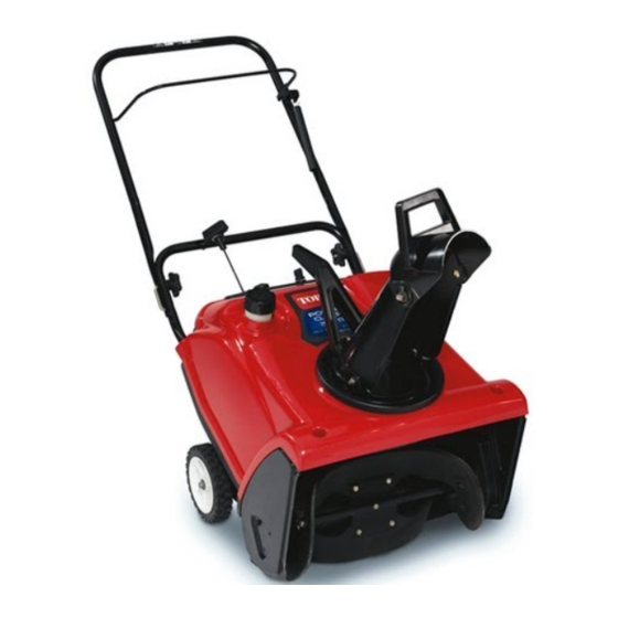
- Page 1 Form No. 3326-129 CCR 2450 GTS CCR 3650 GTS Snowthrower Model No. 38535—220000001 and Up Model No. 38536—220000001 and Up Model No. 38537—220000001 and Up Model No. 38538—220000001 and Up Operator’s Manual International English (GB)
-
Page 2: Table Of Contents
....... . additional information, contact an Authorized Service Dealer or Toro Customer Service and have the model and Safety . -
Page 3: Safety
Toro. This is the safety alert symbol. It is used to alert you Let the engine and the snowthrower adjust to the to potential personal injury hazards. -
Page 4: Toro Snowthrower Safety
Directive Toro Snowthrower Safety 84/538/EEC. The following list contains safety information specific to Toro products or other safety information that you must Vibration Level know. This unit has a maximum hand-arm vibration level of Rotating rotor blades can injure fingers or hands. Stay 15.5 m/s , based on measurements of identical machines... -
Page 5: Safety And Instruction Decals
Safety and Instruction Decals Safety decals and instructions are easily visible to the operator and are located near any area of potential danger. Replace any decal that is damaged or lost. 94-2561 1. Hot surface; do not touch 2. Stay a safe distance from the machine 94-2577 94-2901... - Page 6 105-3522 (Model 38535) or 105-1963 (Model 38537) 1. Warning—read the 3. Thrown object hazard—keep 5. Primer 7. Ignition on Operator’s Manual bystanders away 6. Ignition off 8. Recoil starter 2. Stay away from moving 4. Push the button parts, and stop the engine...
-
Page 7: Assembly
Curved washers Handle locks Screws Locknuts Washers Installing the discharge chute Discharge chute Chute handle (Models 38535 and 38536 only) Bolts Installing the chute crank (Models 38537 and Locknuts 38538 only) Chute crank and mounting bracket Ignition key Starting and stopping the engine... -
Page 8: Installing The Wheels
Installing the Wheels Installing the Handle 1. Turn the snowthrower onto its left side and place a 1. Cut the plastic tie that secures the control cable to the wood block under the left axle end (Fig. 2). handle (Fig. 4). Figure 4 Figure 2 1. -
Page 9: Installing The Discharge Chute
2. Curved washer (2) 4. Handle lock (2) 4. Insert the loose end of the control cable into the bottom hole in the control bar. Refer to Fig. 7 (Models 38535 and 38536) or Fig. 8 (Models 38537 and 38538). Models 38535... -
Page 10: Installing The Chute Crank
Models 38537 and 38538 Installing the Chute Crank 1. Place the discharge chute over the chute ring, and align Models 38537 and 38538 the hole in the back of the discharge chute with the center hole in the chute ring (Fig. 10). 1. -
Page 11: Before Starting
Oil below 32 F (0 C) requires additional mixing. away from an open flame or where a spark may 2. Add the full amount of Toro 50:1 2-Cycle Oil (Fuel ignite the gasoline fumes. Stabilizer Added) or an equivalent high grade, NMMA... -
Page 12: Filling The Fuel Tank
3. Install the cap on the fuel container. 4. Shake the container to mix the gasoline and oil thoroughly. 5. Slowly remove the cap and add the remaining amount of gasoline. Filling the Fuel Tank Important Do not overfill the fuel tank. The gasoline-and-oil mixture must have room to expand. -
Page 13: Stopping The Engine
Adjusting the Discharge Chute Caution Models 38535 and 38536 If you leave the snowthrower plugged into a power Move the chute handle left and right to adjust the direction outlet, someone can inadvertently start the of the snow stream (Fig. 13). The chute deflector handle on... -
Page 14: Snowthrowing Tips
Models 38537 and 38538 Do not attempt to clear snow from a crushed-rock or gravel surface. This product is intended for use only on Rotate the chute crank clockwise to move the discharge paved surfaces. chute to the right or counterclockwise to move the chute to In snowy and cold conditions, some controls and the left (Fig. -
Page 15: Maintenance
Maintenance Note: Determine the left and right sides of the machine from the normal operating position. Recommended Maintenance Schedule Maintenance Service Maintenance Procedure Interval Check the control cable both initially and after the first hour of operation; adjust it if necessary. Refer to Adjusting the Control Cable on page 16. Initially Check for loose fasteners and tighten them if necessary. -
Page 16: Adjusting The Control Cable
3. Ensure that a 1/16 to 1/8 in. (2 to 3 mm) gap exists between the control bar and the handle. Refer to the inset in Figure 7 (models 38535 and 38536) or the inset in Figure 8 (models 38537 and 38538). To adjust the cable, go to Adjusting the Cable on page 16. -
Page 17: Replacing The Rotor Blades
Note: Moving the Z-fitting to a hole closer to the spring After extended use, the drive belt may wear and lose its decreases the gap between the control bar and the proper belt tension. Improper belt tension causes the belt to handle;... - Page 18 Removing the Old Rotor Blades 1. Remove the 4 torx screws and the 4 locknuts that secure the outer edges of the rotor blade to the rotor assembly (Fig. 20). m-5538a/m-5059 Figure 21 1. Thick rubber side 3. Thin rubber side 2.
-
Page 19: Replacing The Scraper
Replacing the Scraper Note: If the rotor blades are partially or completely worn, replace the rotor blades when you replace the scraper. This ensures proper snowthrower operation and performance. 1. Stop the engine and wait for all moving parts to stop. m-5061a 2. -
Page 20: Replacing The Drive Belt
5. Pull up on the idler pulley and remove the old drive belt from the rotor pulley, the brake arm assembly, and the engine pulley (Fig. 27). m-3215 Figure 25 1. 0.030 in. (0.76 mm) 10. Install the spark plug by hand and then torque it to 15 ft-lb (20.4 N m). -
Page 21: Storage
Preparing the Fuel System 1. Add a fuel stabilizer/conditioner to the fuel in the fuel tank as directed. Note: If you use Toro 50:1 2-Cycle Oil (Fuel Stabilizer Added), you do not need to add a fuel m-5537 stabilizer/conditioner. -
Page 22: Troubleshooting
Troubleshooting Toro designed and built your snowthrower for trouble-free operation. Check the following components and items carefully, and refer to Maintenance on page 15 for more information. If a problem continues, contact an Authorized Service Dealer. Problem Possible Causes Corrective Action Electric starter does not turn 1. - Page 23 Problem Possible Causes Corrective Action Engine runs, but the snowthrower 1. You are walking too fast or too 1. Change your walking speed. discharges snow poorly or not at slow. 2. You are trying to remove too 2. Reduce the amount of snow much snow per swath.
Need help?
Do you have a question about the 38535 and is the answer not in the manual?
Questions and answers