
Related Manuals for Axis P55-E Series


Summary of Contents for Axis P55-E Series
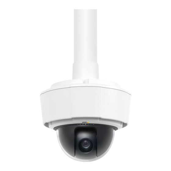
- Page 1 AXIS P55-E Network Camera Series AXIS P5514-E PTZ Network Camera AXIS P5515-E PTZ Network Camera Installation Guide...
- Page 2 2 . Every care has been taken in the preparation of this • Low Voltage (LVD) Directive 2006/95/EC. See Safety document. Please inform your local Axis office of any on page 3 . inaccuracies or omissions. Axis Communications AB cannot •...
- Page 3 FAQ database. Search by product, category, or phrase Japan • report problems to Axis support staff by logging in to この装置は、クラスA 情報技術装置です。この装 your private support area 置を家庭環境で使⽤すると電波妨害 を引き起こす •...
-
Page 5: Hazard Levels
AXIS P55-E Network Camera Series Safety Information Read through this Installation Guide carefully before installing the product. Keep the Installation Guide for future reference. Hazard Levels Indicates a hazardous situation which, if not avoided, will result in DANGER death or serious injury. - Page 6 Battery The Axis product uses a 3.0 V BR/CR2032 lithium battery as the power supply for its internal real-time clock (RTC). Under normal conditions this battery will last for a minimum of five years. Low battery power affects the operation of the RTC, causing it to reset at every power-up. When the battery needs replacing, a log message will appear in the product’s server report.
-
Page 7: Dome Cover
WARNING • Risk of explosion if the battery is incorrectly replaced. • Replace only with an identical battery or a battery which is recommended by Axis. • Dispose of used batteries according to local regulations or the battery manufacturer's instructions. -
Page 9: Installation Steps
AXIS P55-E Network Camera Series Installation Guide This Installation Guide provides instructions for installing AXIS P5514-E/P5515-E PTZ Dome Network Camera on your network. For other aspects of using the product, see the User Manual available at www.axis.com Installation Steps 1. Make sure the package contents, tools and other materials necessary for the installation are in order. - Page 10 AXIS P55-E Network Camera Series Control button SD card slot Status indicator LED Restart button Part number (P/N) & serial number (S/N). Serial number may be required during installation. Screws (3) Sunshield Hook for safety wire Top cover screws (4) 10.
-
Page 11: Led Indicators
• Resetting the product to factory default settings. See page 17. • Connecting to an AXIS Video Hosting System service or AXIS Internet Dynamic DNS Service. For more information about these services, see the User Manual. Restart Button Press the restart button to restart the product. -
Page 12: Specifications
• Risk of data loss. To prevent data corruption, the SD card should be unmounted before removal. To unmount, go to Setup > System Options > Storage > SD Card and click Unmount. This product supports SD/SDHC/SDXC cards (not included). For SD card recommendations, see www.axis.com Specifications Operating Conditions Classification... -
Page 13: Install The Hardware
A standard or high capacity SD card (not included) can be used to store recordings locally in the product. See page 14. • To install the product using a compatible bracket from AXIS T91A Mounting Accessories (sold separately), see page 15. Remove the Protective Packaging See Hardware Overview on page 9 for location of components. -
Page 14: Replace The Dome Cover
AXIS P55-E Network Camera Series 3. To replace the clear/smoked dome cover, see page 14. To install an SD card see page 14. 4. Put the top cover back in its original position and fasten two diagonally opposite screws first (torque < 0.7 Nm), and then the two other screws. - Page 15 • Be careful not to damage the network cable when connecting it. Note For installation with AXIS T91G61 Wall Mount or AXIS T91L61 Wall-and-Pole Mount, use AXIS T91G61/T91L61 Screw Kit (included). 1. Install the mount (not included) according to the instructions supplied with the mount.
- Page 16 AXIS P55-E Network Camera Series Network connector – RJ45 Push-pull Connector (IP66) Network connector and network connector shield Ground screw T20 Washer Cable shoe 5. Attach the grounding wire (torque 1.5 to 2 Nm) to the cable shoe using cable shoe pliers.
-
Page 17: Access The Product
> System Options > Maintenance. Further Information The User Manual is available at www.axis.com Visit www.axis.com/techsup to check if there is updated firmware available for your network product. To see the currently installed firmware version, go to Setup > About. -
Page 18: Warranty Information
AXIS P55-E Network Camera Series Visit Axis learning center www.axis.com/academy for useful trainings, webinars, tutorials and guides. Warranty Information For information about Axis’ product warranty and thereto related information, see www.axis.com/warranty/... - Page 20 Installation Guide Ver. M2.2 AXIS P55-E Network Camera Series Date: September 2017 © Axis Communications AB, 2015 - 2017 Part No. 63068...
Need help?
Do you have a question about the P55-E Series and is the answer not in the manual?
Questions and answers