
Related Manuals for Dell PowerVault MD3860i


Summary of Contents for Dell PowerVault MD3860i
- Page 1 Dell PowerVault MD3860i Storage Arrays Owner's Manual Regulatory Model: E08J Series Regulatory Type: E08J001...
- Page 2 WARNING: A WARNING indicates a potential for property damage, personal injury, or death. Copyright © 2015 Dell Inc. All rights reserved. This product is protected by U.S. and international copyright and intellectual property laws. Dell and the Dell logo are trademarks of Dell Inc.
-
Page 3: Table Of Contents
Contents 1 About your system....................6 ............................6 Introduction ................6 Dell PowerVault Modular Disk Storage Manager ........................6 Related Documentation ..........................7 Front-Panel Features ......................... 8 Front-Panel Indicators ..........................10 Back-Panel Features ..................11 Cooling Fan Module LED Indicator Codes ................12 Power Supply Module Features And Indicators .......................13... - Page 4 ..........................29 SAS Chain Cables ....................30 Removing The SAS Chain Cable(s) ....................31 Installing The SAS Chain Cable(s) ........................32 RAID Controller Modules ............32 Removing A RAID Controller Module Or Expansion Module ............33 Installing A RAID Controller Module Or Expansion Module ..................
- Page 5 ....................... 50 Locating your system service tag ........................... 50 Contacting Dell ........................50 Documentation feedback...
-
Page 6: About Your System
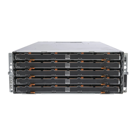
The Dell PowerVault MD3860i RAID storage array (10 Gbps iSCSI) is a 4U rack-mounted system, capable of accommodating up to sixty 3.5 inch or 2.5 inch physical disks. You can expand the number of physical disks up to a maximum of 120 disks (180 disks with premium feature kit), by daisy-chaining your storage enclosure with up to two MD3060e SAS based expansion enclosures. -
Page 7: Front-Panel Features
Dell PowerVault MD 34xx and 38xx Series Support Matrix — Provides information about the software and hardware compatibility matrices for the storage array. • For the full name of an abbreviation or acronym used in this document, see the Glossary at dell.com/ support/manuals. •... -
Page 8: Front-Panel Indicators
Front-Panel Indicators Figure 2. Front-Bezel Indicators Figure 3. Front-Panel Indicators... - Page 9 Item Indicator Icon Description Power-on indicator The power-on indicator lights green when at least one power supply module is supplying power to the storage enclosure. Standby power indicator The standby power indicator lights green when the system is in standby mode and the main power is off.
-
Page 10: Back-Panel Features
Indicates that there is no power reaching the drive or a drive is not installed. Back-Panel Features NOTE: The following illustration displays the Dell PowerVault MD3860i storage enclosure. Figure 4. Back-Panel Features cooling fan module (2) power supply switch (2) -
Page 11: Cooling Fan Module Led Indicator Codes
Cooling Fan Module LED Indicator Codes Figure 5. Cooling Fan Module Indicators Item Indicator Icon Description Power indicator The power indicator lights green when power to the cooling fan module is available. Service action required The Service action required indicator lights amber indicator when there is a fault in the cooling fan module. -
Page 12: Power Supply Module Features And Indicators
Power Supply Module Features And Indicators NOTE: Your storage array is shipped with two IEC C19 to C20 jumper cords. Connect the C19 plug to the array's power supplies and the C20 plug to the power distribution unit (PDU) in the rack cabinet. -
Page 13: Physical-Disk Led Indicators
Item Indicator or Connector Icon Description Indicates that you cannot remove the power supply module from the system. Service action required The service action required indicator lights amber indicator when there is a fault in the power supply module. AC power indicator Green Indicates that AC output voltage is within the limit. - Page 14 Item Indicator Icon Description Service action allowed CAUTION: Remove the physical disk from indicator the system only if the service action allowed indicator lights blue. Removing the physical disk from the system when the service action allowed indicator is off may damage the system.
-
Page 15: Controller Modules
Controller Modules RAID Controller Modules RAID controller modules provide high-performance, advanced virtual disk configuration, and fault- tolerant disk subsystem management. Each RAID controller module contains 4 GB of mirrored cache for high availability and is protected by a battery powered cache offload mechanism. NOTE: 8 GB mirrored cache is an optional feature. -
Page 16: Expansion Controller Modules
12 Gbps SAS IN port (2) Provides host-to-controller SAS connection. USB port Reserved port. Mini USB port Dell support only. Password reset switch Pressing this switch resets the password. SAS expansion port (2) Provides SAS OUT connection for cabling to a daisy chained expansion enclosure. -
Page 17: Md3060E Expansion Module Features And Indicators
Provides EMM to RAID controller SAS connection. SAS IN port 1 Provides EMM to RAID controller SAS connection. Serial debug port Dell support only. Telnet port Dell support only. SAS OUT port Provides SAS connection for cabling to a downchain expansion enclosure. -
Page 18: Raid Controller Module-Additional Features
To reset the password, push and hold down the password reset switch for at least five seconds. The password is deleted. You can change the password using MD Storage Manager. For more information about setting your password, see the Dell PowerVault MD Series Storage Arrays Administrator's Guide at dell.com/powervaultmanuals. -
Page 19: Installing And Removing System Components
Installing and removing system components Recommended Tools You may need the following items to perform the procedures in this section: • #2 Phillips screwdriver • T8 and T15 Torx screwdrivers • Wrist grounding strap connected to ground Removing And Installing The Front Bezel Installing The Front Bezel You must install the front bezel on the system to secure the disk drawers against accidental removal. -
Page 20: Removing The Front Bezel
Figure 10. Removing and Installing the Front Bezel release latches (2) front bezel guide pins (4) Removing The Front Bezel You must remove the front bezel to access the disk drawers, which enables you to remove and install physical disks in the system. Press the release latch on either side of the front bezel. -
Page 21: Opening The Physical-Disk Drawer
Damage due to servicing that is not authorized by Dell is not covered by your warranty. Read and follow the safety instructions that came with the product. -
Page 22: Closing The Physical-Disk Drawer
Damage due to servicing that is not authorized by Dell is not covered by your warranty. Read and follow the safety instructions that came with the product. - Page 23 For more information, see the Dell PowerVault MD Series Storage Arrays Administrator's Guide at dell.com/powervaultmanuals. Remove the front bezel. Remove both the SAS cable chains from the back of the chassis. Open the physical-disk drawer. CAUTION: Do not try to remove more than one drawer at a time. Ensure that you insert the drawer that is out completely before pulling out another drawer.
-
Page 24: Installing The Physical-Disk Drawer
Damage due to servicing that is not authorized by Dell is not covered by your warranty. Read and follow the safety instructions that came with the product. -
Page 25: Physical Disks
• The MD Series Dense storage array and expansion enclosure support mixing of physical disk types. NOTE: 15k RPM SAS drives are not supported. For the latest drive support, refer to Dell PowerVault MD 34xx/38xx Series Support Matrix at: dell.com/powervaultmanuals. - Page 26 Figure 15. Removing and Installing the 2.5 Inch Physical Disk in a 2.5 Inch Physical-Disk Carrier 2.5 inch physical drive cage guide pin (4) release handle holes on physical disk (4) carrier for 2.5 inch physical disk 2.5 inch physical disk...
-
Page 27: Installing A Physical Disk In A Physical-Disk Carrier
Damage due to servicing that is not authorized by Dell is not covered by your warranty. Read and follow the safety instructions that came with the product. -
Page 28: Removing A Physical Disk From A Physical-Disk Drawer
Damage due to servicing that is not authorized by Dell is not covered by your warranty. Read and follow the safety instructions that came with the product. -
Page 29: Installing A Physical Disk In A Physical-Disk Drawer
Damage due to servicing that is not authorized by Dell is not covered by your warranty. Read and follow the safety instructions that came with the product. -
Page 30: Removing The Sas Chain Cable(S)
Damage due to servicing that is not authorized by Dell is not covered by your warranty. Read and follow the safety instructions that came with the product. -
Page 31: Installing The Sas Chain Cable(S)
Damage due to servicing that is not authorized by Dell is not covered by your warranty. Read and follow the safety instructions that came with the product. -
Page 32: Raid Controller Modules
Damage due to servicing that is not authorized by Dell is not covered by your warranty. Read and follow the safety instructions that came with the product. -
Page 33: Installing A Raid Controller Module Or Expansion Module
Damage due to servicing that is not authorized by Dell is not covered by your warranty. Read and follow the safety instructions that came with the product. -
Page 34: Opening The Raid Controller Module
Damage due to servicing that is not authorized by Dell is not covered by your warranty. Read and follow the safety instructions that came with the product. -
Page 35: Raid Controller Module Backup Battery Unit
Damage due to servicing that is not authorized by Dell is not covered by your warranty. Read and follow the safety instructions that came with the product. -
Page 36: Installing The Raid Controller Module Backup Battery Unit
Damage due to servicing that is not authorized by Dell is not covered by your warranty. Read and follow the safety instructions that came with the product. -
Page 37: Installing A Power Supply Module
Damage due to servicing that is not authorized by Dell is not covered by your warranty. Read and follow the safety instructions that came with the product. -
Page 38: Cooling Fan Modules
Damage due to servicing that is not authorized by Dell is not covered by your warranty. Read and follow the safety instructions that came with the product. -
Page 39: Installing A Cooling Fan Module
Damage due to servicing that is not authorized by Dell is not covered by your warranty. Read and follow the safety instructions that came with the product. -
Page 40: Troubleshooting Your System
Damage due to servicing that is not authorized by Dell is not covered by your warranty. Read and follow the safety instructions that came with the product. -
Page 41: Troubleshooting Power Supply Modules
Damage due to servicing that is not authorized by Dell is not covered by your warranty. Read and follow the safety instructions that came with the product. -
Page 42: Troubleshooting Expansion Enclosure Management Modules
Damage due to servicing that is not authorized by Dell is not covered by your warranty. Read and follow the safety instructions that came with the product. -
Page 43: Troubleshooting Physical Disks
Damage due to servicing that is not authorized by Dell is not covered by your warranty. Read and follow the safety instructions that came with the product. -
Page 44: Troubleshooting A Wet Storage Array
Damage due to servicing that is not authorized by Dell is not covered by your warranty. Read and follow the safety instructions that came with the product. -
Page 45: Critical Conditions
A physical disk in a redundant virtual disk has failed Invalid Storage Array The RAID controller module is supported only in a Dell-supported storage array. After installation in the storage array, the controller performs a set of validation checks. The array status LED is lit with a steady amber color while the RAID controller module completes these initial tests and the controllers are booted successfully. -
Page 46: Pci Errors
PCI Errors The storage array firmware can detect and only recover from PCI errors when the RAID controller modules are configured for redundancy. If a virtual disk uses cache mirroring, it fails over to its peer RAID controller module, which initiates a flush of the dirty cache. -
Page 47: Technical Specifications
RAID controller modules Two hot-swappable modules with temperature sensors 4 GB or 8 GB of cache per controller Dell PowerVault MD3860i storage arrays Provides host-to-controller 10 Gbps iSCSI connection and two 12 Gbps SAS connections Expansion Modules Dell PowerVault MD3060e expansion enclosures... - Page 48 IT power systems with a phase to phase voltage not exceeding 230 V. Battery 6.6 V DC, 1100 mAh, 7.26 W Lithium ion battery Environmental NOTE: For additional information about environmental measurements for specific system configurations, see dell.com/environmental_datasheets. Temperature...
- Page 49 1 °C/300 m (1 °F per 550 ft) above 900 m (2952.75 ft). NOTE: For information on supported expanded operating temperature range and configurations, see the Owner's Manual at dell.com/support/ manuals. Storage –40 °C to 65 °C (–40 °F to 149 °F) with a maximum temperature gradation of 20 °C per hour...
-
Page 50: Getting Help
Code and Service Tag are found on the front of a physical DR Series system by pulling out the information tag. This can also be found on the support tab in the GUI. This information is used by Dell to route support calls to the appropriate personnel.
Need help?
Do you have a question about the PowerVault MD3860i and is the answer not in the manual?
Questions and answers