Table of Contents
Advertisement
Advertisement
Table of Contents

Related Manuals for Honeywell Dolphin 6510

Summary of Contents for Honeywell Dolphin 6510
- Page 1 ™ Dolphin 6510 Mobile Computer ® with Windows CE 6.0 User’s Guide...
- Page 2 Disclaimer Honeywell International Inc. (“HII”) reserves the right to make changes in specifications and other infor- mation contained in this document without prior notice, and the reader should in all cases consult HII to determine whether any such changes have been made. The information in this publication does not rep- resent a commitment on the part of HII.
-
Page 3: Table Of Contents
Top Panel Features ......................3-10 Bottom Panel Features ...................... 3-11 Dolphin Peripherals/Accessories for the Dolphin 6510 ............ 3-12 USB Communication Cable for the Dolphin 6510 ............. 3-12 Li-ion Battery Packs ......................3-12 Battery Power ........................3-12 Resetting the Terminal ...................... 3-15 Soft Reset (Warm Boot) .................. - Page 4 Chapter 4 - Using the Keypad Overview ........................4-1 Navigation Keys ......................4-1 Basic Keys ........................4-2 Alpha/Numeric Modes ....................4-2 Alpha Indicators on the Number Keys..............4-2 Function Key Combinations ..................4-3 CTRL Key Combinations ....................4-4 Program Buttons ......................4-5 Chapter 5 - Using the Image Engine Overview ........................
- Page 5 QuadCharger Device ....................9-1 Battery Charging ......................9-2 Recommendations for Storing Batteries ............... 9-3 Troubleshooting ......................9-2 Technical Specifications....................9-4 Chapter 10 - Dolphin 6500 Net Base Device (Model 6500-NB) Overview ........................10-1 Parts and Functions ....................10-2 Front Panel ......................10-2 Back Panel ......................
-
Page 6: Chapter 1 - Agency Approvals
Agency Approvals Label Locations Dolphin 6510 mobile computers meet or exceed the requirements of all applicable standards organizations for safe operation. However, as with any electrical equipment, the best way to ensure safe operation is to operate them according to the agency guidelines that follow. -
Page 7: Chapter 2 - Getting Started
Initial Setup for Dolphin 6510 Terminals Step 1. Install the Battery The Dolphin 6510 is shipped with the battery packaged separate from the unit. Follow the steps below to install the battery. 1. Release the strap making it convenient to reach the cover. -
Page 8: Led Indicators
We recommend use of Honeywell Li-Ion battery packs. Use of any non-Honeywell battery may result in damage not covered by the warranty. Step 2. Charge the Batteries Dolphin 6510s ship with the battery pack significantly discharged of power. Charge the battery pack with the Dolphin charging cable until the LED turns green (red while charging). - Page 9 The power adapter on the power cable converts the voltage from the power source to 5 volts DC. Only power adapter cables from Honeywell convert the voltage appropriately. The power cable contains a plug adapter for each geography (US, UK, EU, etc.).
-
Page 10: Command Bar Icons
Shows signal strength of WiFi radio. (A red X indicates it is not currently associated to an AP.) Double tap to configure your WLAN Secure Wireless Client. For complete configuration instructions, download the Honeywell Secure Wireless (SWC) Client User’s Guide from www.honeywellaidc.com. -
Page 11: Using The Stylus
Using the Stylus The terminal comes with a stylus included in a loop on the hand strap. Use this stylus (or your finger) to select or enter information on the touch screen. The stylus functions as a mouse; generally, a tap is the same as a click. -
Page 12: Chapter 3 - Hardware Overview
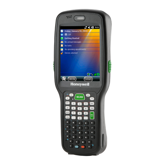
Hardware Overview Dolphin 6510 terminals include a number of standard terminal configurations as well as charging and communication peripherals and accessories to maximize the efficiency of your application setting. Standard Terminal Configurations Dolphin 6510 configurations: WPAN/WLAN configuration has both a Bluetooth radio and an 802.11a/b/g/n radio. -
Page 13: Front Panel Features
The LED lights green when the main battery charging is completed. The LED lights blue during soft and hard resets. The LED is user-programmable. Please refer to the explanation in the SDK document. Honeywell D6x10 Device SDK for Windows CE 6.0 > Visual C++ Development > Device API > Functions > devSetLEDState Keypad 28-key numeric keypad (alpha shifted) and 52-key full alphanumeric keypads are available. -
Page 14: Display Backlight
The duration of backlight of keypad synchronizes with LCD backlight’s. Using Screen Protectors Honeywell defines proper use of the terminal touch panel display as using a screen protector and proper stylus. Screen protectors maintain the ongoing integrity (i.e., prevent scratching) of the touch panel, which is why their use is recommended for applications that require a high to medium level of interface with the touch panel. - Page 15 Replacement screen protectors can be purchased directly from Honeywell. Contact a Honeywell sales representative for details. Honeywell also mandates use of a proper stylus, which is one that has a stylus tip radius of no less than 0.8mm. Use of the Honeywell stylus included with the terminal is recommended at all times.
- Page 16 3. Release the left edge of the backing paper on the screen protector. 4. Align the exposed edge of the screen protector along the left edge of the touch panel. Make sure that it lies flush with edges of the touch panel. Backing Paper Screen Protector...
- Page 17 8. Verify that the screen accepts input from the stylus as usual. If not, re-apply the screen protector. 9. Press the red Power button to put the terminal back in Suspend Mode on the 28-key Dolphin 6510 or press the Blue then Z (Power) keys on the 52-key Dolphin 6510.
- Page 18 12. For maximum performance, recalibrate the screen. Tap Start > Settings > Control Panel > double tap Stylus > Calibration tab. 13. Tap Recalibrate and follow the instructions on the screen.
-
Page 19: Back Panel Features
Rear Scan Button The Dolphin 6510 has a Scan button conveniently located on the back of the unit. This button works like the SCAN button located on the front of the unit. Pressing this button can also resume a suspended device. - Page 20 Stylus Dolphin 6510 terminals ship with a stylus inserted in a loop on the hand strap. Store the stylus in the hand strap when you’re not using it; see Using the Stylus on page 2-5. Installing Memory Cards The Dolphin 6510 supports Secure Digital (SD) memory cards from 512MB up to 8GB in capacity. The ®...
-
Page 21: Left Side Panel Features
Left Side Panel Features Side Button Headset Jack Side Button There is a button like this on both side panels. You can use the Programs Buttons option in the Control Panel to change the functionality of the side buttons. Headset Jack The rubber door on the right side panel provides access to the headset jack. -
Page 22: Bottom Panel Features
I/O Connector The I/O mechanical connector is designed to work exclusively with Dolphin 6510 peripherals and cables. This connector powers the terminal, charges the main battery, and facilitates communication. This connector supports high speed USB 2.0 communication (12 Mbps to 480 Mbps) and RS-232 communications with a maximum speed of 115Kbps and seven baud rate settings. -
Page 23: Dolphin Peripherals/Accessories For The Dolphin 6510
Both batteries work together to prevent data loss when the terminal is used over long periods of time. Both batteries must be charged to full capacity before using the Dolphin 6510 for the first time! Charge the main battery pack with the Dolphin charging cable until the LED turns green (red while charging). - Page 24 Changing the Main Battery Pack Before installing a battery pack, press the Power button on the 28-key Dolphin 6510 or press the Blue then Z ( Power) keys on the 52-key Dolphin 6510 to put the terminal in Suspend Mode (see page 3-16) so that operations are suspended before removing the main power source.
- Page 25 Note: If the main battery is low and the terminal is in Suspend Mode, pressing the button does wake the Dolphin 6510 terminal; you must first replace the discharged battery with a fully charged battery or apply A/C power to the terminal. Checking Battery Power Power icons appear in the command bar at the bottom of the window.
-
Page 26: Resetting The Terminal
• Although your battery can be recharged many times, it will eventually be depleted. Replace it after the battery is unable to hold an adequate charge. • If you are not sure the battery or charger is working properly, send it to Honeywell International or an authorized service center for inspection. -
Page 27: Soft Reset (Warm Boot)
To suspend operation, press the red Power button to put the terminal in Suspend Mode on the 28-key Dolphin 6510 or press the Blue then Z ( Power ) keys on the 52-key Dolphin 6510. To wake the device, press the Power button. You may also press the front or rear scan keys to wake a suspended device. -
Page 28: Care And Cleaning Of The Dolphin Terminal
The terminal can be cleaned with a damp cloth. Dolphin 6510 Technical Specifications Operating System Microsoft Windows CE 6.0 Development Honeywell SDK for Windows® CE 6.0 Environment Application Software Honeywell Power Tools and Demos Processor TI Cortex-A8 1GHz... - Page 29 Backup Battery 140mAh Li-ion Polymer. Expected Hours of 3300mAh battery pack: 22 hours (with scan every 2 seconds) Operation Battery life varies with application and use case Charging 5V/2A input through bottom access DC or USB/Serial connector Expected Charge Time 3300mAh - 5 1/2 hours for a fully depleted battery Charging Peripherals AC wall adapter and Charger (PSC11R-050)/Communication Cable...
-
Page 30: Chapter 4 - Using The Keypad
Using the Keypad Overview The 28-key and 52-key keypads are as follows: 28-key keypad (numeric) 52-key keypad (full alphanumeric) Navigation keys (arrow keys) Navigation keys Power key Power key combination Navigation Keys The navigation keys enable you to move the cursor up and down lines and from character to character. -
Page 31: Basic Keys
Basic Keys Name Function ALPHA (28-key) Toggles the keyboard between alpha (upper and lowercase) and numeric SFT (52-key) modes on the 28-key keypad. The “ABC”/”abc” indicator on the command bar changes accordingly. Pressing SFT two times in rapid succession on a 52-key keypad toggles between upper and lowercase. -
Page 32: Function Key Combinations
Note that when typing in alpha mode on the 28-key Dolphin 6510, you must use the same multi-press method you would use when typing letters on a phone keypad. Each key press types the next letter in the sequence as displayed by the alpha indicator. -
Page 33: Ctrl Key Combinations
52-key Function Key Combination FUNC + 9 FUNC + 10 FUNC PG Page up or down - used in conjunction with Up and Down arrows CTRL Key Combinations On the 28-key keypad, hold down the Control key ( CTRL ) and then press a key with the red characters below it to type the desired character. -
Page 34: Program Buttons
52-key Function Key Combination CTRL + G CTRL + H “ CTRL + I CTRL + K CTRL + L CTRL + M CTRL + N CTRL + P – CTRL + Q CTRL + U Windows Explorer CTRL + . CTRL + , CTRL + VOL Increase/decrease volume... - Page 35 VOL+ Volume Up VOL- Volume Down WINDOW Start Menu key Delete CALIB Touch Calibration No Action No Action No Action No Action No Action No Action No Action No Action No Action No Action No Action...
-
Page 36: Chapter 5 - Using The Image Engine
Using the Image Engine Overview The Dolphin 6510 houses a compact image engine using Adaptus ™ Imaging Technology that instantly reads all popular 1D and 2D bar codes and supports omni-directional aiming and decoding. The image engine can also capture digital images, such as signatures and pictures. -
Page 37: Supported Bar Code Symbologies
Supported Bar Code Symbologies Symbology Type Symbology Name Codabar Interleaved 2 or 5 1D Symbologies Code 3 of 9 Matrix 2 of 5 Code 11 Code 32 Pharmaceutical (PARAF) Code 93 Straight 2 of 5 IATA Code 128 Straight 2 of 5 Industrial EAN with Add-On Telepen EAN with Extended Coupon Code... -
Page 38: Activating The Engine
Activating the Engine When a scanning application is open, press the Scan key to activate the image engine. Using Demos Dolphin Demos are software utilities loaded on all Dolphin terminals that demonstrate the advanced features of the terminal. There are two Demos that feature the image engine: Image Demo and Scan Demo. - Page 39 Sample Bar Codes You can use the following bar codes to verify decoding: Sample 128 Sample PDF417 Code 128 PDF417 Test Message Omni-Directional Scanning Positions The high-vis aiming pattern frames the bar code to provide you with the best scanning performance. Note: To achieve the best read, the aiming beam should be centered horizontally across the bar code.
-
Page 40: Capturing Images
Capturing Images The image-capture process is an intuitive, split-second operation for experienced users. By following basic guidelines, however, new users can easily develop their own technique and, with practice, quickly learn to adapt to different application environments. Image Preview When the imaging process is initiated, the touch screen displays a preview of the object. This is a live video image of what the imager is currently viewing and has a slightly degraded appearance compared to the captured image. -
Page 41: Chapter 6 - System Settings
6-6. Installing Additional Software Dolphin terminals ship with the operating system, radio drivers, and custom Honeywell software already installed. These are the default programs that install when your terminal first boots up. You can install additional software programs on the terminal provided that the following parameters are met: •... - Page 42 Connecting the USB Charging/Communication Cable for the Dolphin 6510 Slide the USB cable unit onto the bottom of the terminal lining up the terminal’s I/O connector to the cable unit’s connector to facilitate USB communication between the Dolphin terminal and the host workstation.
-
Page 43: Activesync Communication
When communicating via ActiveSync, your terminal is designed to be connected to the host workstation with a Honeywell communication peripheral. We recommend use of Honeywell peripherals, power cables, and power adapters. Use of any non-Honeywell peripherals, cables, or power adapters may cause damage not covered by the warranty. -
Page 44: Setting Up The Dolphin Terminal
Setting Up the Dolphin Terminal The Dolphin terminal defaults to USB communication out of the box. To verify and/or change the default setting, tap Start > Settings > Control Panel > PC Connection. Must be checked to connect to a workstation Displays the current connection setting Tap to change the connection settings Tap Change Connection to change the current settings. - Page 45 Exploring the Terminal from the Workstation When the terminal and desktop computer are connected, open the main ActiveSync window (on the desktop), and click Explore. The Mobile Device folder opens in Windows Explorer. The Dolphin terminal is now treated as a mass storage device, and transferring files is as simple as dragging and dropping or copying and pasting as you would for moving files between folders on your hard drive.
-
Page 46: Wireless Radios
Program Files folder on the terminal. If you want the program to persist through hard resets, paste the program to the Autoinstall folder \Honeywell\AutoInstall 3. On the terminal Desktop, tap My Device and, in Windows Explorer, navigate to the folder where the program is located. -
Page 47: Adding Programs From The Internet
Configuring the WLAN Radio The WLAN radio is configured in the Honeywell WLAN Security Supplicant, which you access by double tapping the program icon in the command bar. For complete configuration instructions, download the Honeywell Secure Wireless (SWC) Client User’s Guide from www.honeywellaidc.com. -
Page 48: Chapter 7 - Bluetooth Handler
Connecting Bluetooth devices usually requires that they be paired; the same passkey must be entered for each device. If you want to connect the Dolphin 6510 to a device without any input method (e.g., printers, headsets), refer to the user documentation that accompanied the device for pairing information. -
Page 49: Setting Up A Connection To A Mobile Phone
GPRS data transfer and if it has an available Bluetooth connection. If your phone supports 3G data transfer, you should be able to connect the Dolphin 6510 to your phone. 1. Determine if your phone is configured and connected to GPRS. -
Page 50: Overview
Note: The information in this chapter applies to both the Dolphin HomeBase and Dolphin eBase devices unless otherwise indicated. As the hub of your Dolphin 6510 system, the Dolphin HomeBase charging and communication cradle supports high-speed USB 2.0 and RS-232 communication with a workstation. The Dolphin eBase is identical to the Dolphin HomeBase except it supports Ethernet communication as well as USB 2.0, and RS-232. -
Page 51: Front Panel
Front Panel Terminal Well Charging LED Terminal Well Place the Dolphin terminal in the terminal well to communicate with a host device, power the terminal, and charge the terminal’s battery. Make sure that the device is securely seated. Rubber Feet The bottom panel has four rubber feet to stabilize the unit on a flat surface. -
Page 52: Back Panel
Back Panel HomeBase eBase Serial Port Serial Port USB Port USB Port Ethernet Port DC Power Jack DC Power Jack DC Power Jack Connect the power cable to this power jack; see Powering the Dolphin HomeBase Device page 8-4. USB Port The USB port is High-speed (v2.0). - Page 53 (see Communicating with the Dolphin Terminal / Synchronizing with the Host Workstation on page 6-4). Honeywell recommends that you leave the base connected to its power source at all times, so that it is always ready to use. eBase Clamp-on Ferrite Core Installation We recommend that you install the clamp-on ferrite core included with your Dolphin®...
-
Page 54: Charging The Main Battery
The following illustration shows how to install the ferrite on the cable. It should be placed approximately 1.57 inches (40mm) from the RJ45 plug. The cable should be looped around the core, as shown. Charging the Main Battery The base powers the terminal and fully charges its main battery pack in an average of 5 1/2 hours for a fully depleted battery. - Page 55 Charging a Spare Battery The base can also charge a second battery while the terminal is positioned in the base. The second battery can be inserted in the battery charging well in back of the terminal connection. Place the battery in the well with the label facing up and toward the back of the unit.
-
Page 56: Technical Specifications
Technical Specifications Structural Dimensions 5.3 in. high X 4.5 in. wide X 3.1 in. deep (13.5 cm. X 11.4 cm. X 7.9 cm.) Weight Dolphin HomeBase - 11.0 oz. (313g) Dolphin eBase - 11.3 oz (320g) Material Polycarbonate Color Black Environmental Operating Temperature 14°... -
Page 57: Chapter 9 - Dolphin Quadcharger Device
We recommend use of Honeywell peripherals, power cables, and power adapters. Use of any non-Honeywell peripherals, cables, or power adapters may cause damage not covered by the warranty. We recommend use of Honeywell Li-Ion battery packs. Use of any non-Honeywell battery may result in damage not covered by the warranty. -
Page 58: Battery Charging
Battery Charging Charging Process This charger charges Dolphin 6510 Li-Ion 3300mAh packs in an average of 5 1/2 hours for a fully depleted battery. It takes less time if the battery has some charge. Each charging slot works independently of the other three. -
Page 59: Recommendations For Storing Batteries
3. When the Status LED turns green, the battery in the slot has completed charging. Recommendations for Storing Batteries To maintain top performance from batteries, follow these storage guidelines: • Avoid storing batteries outside of the specified temperature range of -4 to 104° F (-20 to 40° C) or in extremely high humidity. -
Page 60: Technical Specifications
Technical Specifications Structural Dimensions 7.3 in. long X 3.7 in. wide X 2.4 in. high (18.5 cm. X 9.4 cm. X 6.1 cm.) Weight 11.5 oz. (325g) Material Case: Polycarbonate Color: Black Capacity Supports up to four Li-Ion battery packs Environmental Operating Temperature 32°... -
Page 61: Chapter 10 - Dolphin 6500 Net Base Device (Model 6500-Nb)
Dolphin 6500 Net Base Device Overview The Net Base enables up to four Dolphin 6510 mobile computers to communicate with a host device over an Ethernet network. In addition, the Net Base provides a second RJ45 Ethernet port for connec- tion to an additional device such as a printer, workstation, eBase, or another Net Base. -
Page 62: Parts And Functions
Parts and Functions Front Panel Terminal Wells Power/Dock LED COMM LED Terminal Wells The Net Base contains four terminal wells. Each well has its own dedicated Power/Dock LED and COMM LED indicator. Place the Dolphin terminal in any one of the four wells to communicate with a host device, power the terminal, and charge the installed battery pack. -
Page 63: Back Panel
Green LED Yellow LED Two RJ45 Ethernet Ports DC Power Jack DC Power Jack Use the power cable from Honeywell that comes with the Net Base to supply power to this power jack. For more information, see Power on page 10-4. -
Page 64: Bottom Panel
8.5A power supply provided with the Net Base converts the voltage appropriately. The operating temper- ature range is -10° to 50° C (14° to 122° F). Honeywell recommends that you leave the Net Base connected to its power source at all times, so that it is always ready to use. -
Page 65: Charging The Main Battery
Make sure the terminal is dry before placing it in the Net Base. Do NOT place a wet terminal in the Net Base! Doing so may cause damage not covered by the warranty. We recommend use of Honeywell Li-Ion battery packs. Use of any non-Honeywell battery may result in dam- age not covered by the warranty. -
Page 66: Displaying The Net Base Terminal Well And Dolphin Ip Address
3. Plug the Ethernet cable into the network. 4. Insert the Dolphin into one of the terminal wells. The DOCK LED for the well changes from red to green and the connection icon on the Dolphin’s title bar changes from 5. -
Page 67: Bottom Panel
Bottom Panel DIN Rail Slot Rubber Feet, Qty. 6 Desk Mounting The DIN Rail (7.5 X 35 mm) slot on the bottom panel enables secure mounting on a horizontal surface. Hardware Required • 3/16 in. dia x 5/8 in. long pan head screw •... -
Page 68: Wall Mounting
Wall Mounting The optional wall mount bracket enables secure mounting of the base on a vertical surface. The wall mount bracket can be used in conjunction with the DIN rail but does not require the DIN Rail for use. Hardware (Provided) •... - Page 69 2. Slide the bolt through the wall bracket, and thread the toggle nut onto Toggle Nut the bolt. Bolt 3. Press the ends of the toggle nut together, and insert the bolt/nut into the pilot hole until the nut clears inside wall surface. The toggle nut should spring open preventing the screw from being removed.
- Page 70 3. Slide the washer onto the screw and tighten the nut to secure the assembly. Wall Bracket, Qty. 1 Screw, Qty. 2 Washer, Qty. 1 DIN Rail, Qty. 1 Nut, Qty. 1 Washer, Qty. 1 Nut, Qty. 1 4. Remove the rubber feet on the bottom of the Net Base. 5.
-
Page 71: Chapter 11 - Dolphin 6500 Slide-On Handle
Removing the Hand Strap Prior to installing the Dolphin 6510 handle on the terminal, you must remove the hand strap. 1. Release the hook and loop portion of the strap and feed it through the opening at the bottom end of the terminal. -
Page 72: Chapter 12 - Customer Support
• The duration of the limited warranty for batteries is one year. Use of any battery from a source other than Honeywell may result in damage not covered by the warranty. Batteries returned to Honeywell International Inc. in a reduced state may or may not be replaced under this warranty. - Page 73 12-2...
- Page 74 Honeywell Scanning & Mobility 9680 Old Bailes Road Fort Mill, SC 29707 www.honeywellaidc.com 6510-UG Rev C 8/17...
Need help?
Do you have a question about the Dolphin 6510 and is the answer not in the manual?
Questions and answers