
Related Manuals for Wouxun KG-1000M


Summary of Contents for Wouxun KG-1000M
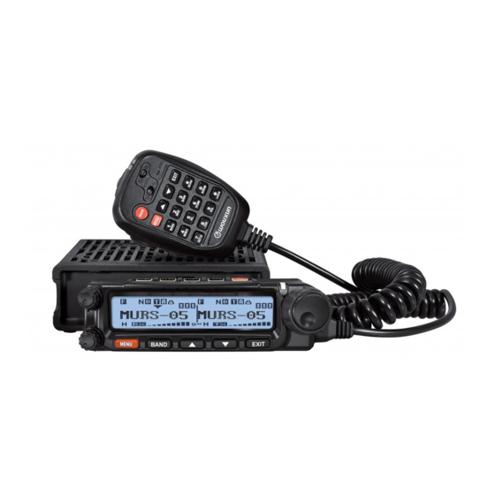
- Page 1 Thank you for purchasing the Wouxun KG-1000M mobile MURS radio. Your feedback makes our products better. Please share your thoughts. feedback@buytwowayradios.com www.buytwowayradios.com...
-
Page 2: Table Of Contents
Contents Safety Information ������������������������������������������������������������������������������������ 8 FCC Licensing Information .................12 Installation and Setup ����������������������������������������������������������������������������� 13 What’s Included ...................13 Transceiver Installation .................14 Connecting a Power Source ................16 Replacing the Fuse ..................17 Connecting an Antenna ................18 Front Panel Installation ................20 External Speakers ..................25 Hand Microphone Installation ..............26 Getting Started ���������������������������������������������������������������������������������������... - Page 3 Back Panel ....................31 Side Panels ....................31 Hand Microphone ..................32 Basic Operation �������������������������������������������������������������������������������������� 33 Introducing MURS and the KG-1000M .............33 Your First Transmit ..................34 Dual Display: Using Areas “A” and “B” ............36 Frequency and Channel Modes ..............37 NOAA Weather Mode .................39 Hand Microphone Hotkeys .................40...
- Page 4 [3: MPOWSET] Medium Power Level ............48 [4: ROGER] Roger Beep ................49 [5: BEEP] Button Beeps................49 [6: VOICE] Voice Guide ................49 [7: BCL] Busy Channel Lockout ..............50 [8: SP-MUTE] Speaker Mute Settings ............50 [9: SC-REV] Scan Method................50 [10: TOT] Transmit Overtime Timer ............51 [11: TOA] Transmit Overtime Alarm ............52 [12: ANI-SW] Caller ID Transmit ..............52 [13: RING] DTMF Prompt Time ...............52...
- Page 5 [17: TX-LED] Transmit LED Color ............54 [18: WT-LED] Standby LED Color ............54 [19: RX-LED] Receive LED Color .............54 [20: DEL-CH] Channel Delete ..............55 [21: CH-NAME] Channel Name Edit ............55 [22: PRICH-SW] Priority Channel On/Off ..........56 [23: SPK-CONT] Speaker Select ..............56 [24: AUTOLOCK] Auto Lock ..............57 [25: RX-CTC] Receive CTCSS Tone ............57 [26: RX-DCS] Receive DCS Tone ..............57...
- Page 6 [31: ALERT] Single Tone Pulse Transmission ..........59 [32: COMPAND] Compander ..............60 [33: FAN-SET] Cooling Fan Settings ............60 [34: LOW-V] Low Voltage Alert ..............60 [35: SCRAM] Descramble ................61 [36: SC-QT] CTCSS/DCS Scan Save Options ..........61 [37: SC-CTC] CTCSS Tone Scanning ............62 [38: SC-DCS] DCS Tone Scanning ............62 [39: SC-GROUP] Scan Group ..............63 [40: RPT-TONE] Repeater Reception Confirmation .........63...
- Page 7 [45: ABR] Backlight ..................65 [46: FM-RADIO] FM Radio ..............66 [47: AUT. AM] AM Detection ..............66 [48: AM-SW] AM On / Off ...............66 Advanced Operation ������������������������������������������������������������������������������� 68 DTMF Encoding ..................68 Setting Non-Standard CTCSS or DCS ............69 Troubleshooting ������������������������������������������������������������������������������������� 72 Technical Information ���������������������������������������������������������������������������� 74 Specifications ....................74 Standard CTCSS and DCS Tones ...............75 Default MURS Channels and Frequencies ...........77...
-
Page 8: Safety Information
Safety Information Safety Information The KG-1000M is an electrical apparatus, as well as a generator of RF (Radio Frequen- cy) energy, and you should exercise all safety precautions as are appropriate for this type of device. These safety tips apply to any device installed in a well-designed radio station. - Page 9 Safety Information Safety Information ⚠ Never allow unsupervised children to play in the vicinity of your mobile radio or antenna installation. ⚠ Be certain to wrap any wire or cable splices thoroughly with insulating electrical tape, to prevent short circuits. ⚠...
- Page 10 Notice ▪ These tips are important for safe operation of your KG-1000M mobile radio and its accessories. If they do not function normal- ly, please get in touch with your dealer immediately. ▪...
- Page 11 Safety Information Safety Information Caution Please read this manual before using, as it includes important instructions for the safe handling, use and operation of your radio. FCC Compliance This device complies with Part 15 of the FCC Rules. Operation is subject to the follow- ing two conditions: (1) This device may not cause harmful interference, and (2) This device must accept any interference received, including interference that may...
-
Page 12: Fcc Licensing Information
DO NOT attempt to use the radio with a damaged antenna or feed line. FCC Licensing Information The Wouxun KG-1000M is FCC Part 95J type accepted for use on MURS. The KG-1000M operates on Multi-Use Radio Service (MURS) frequencies according to the Federal Communications Commission (FCC) Rules in the United States. -
Page 13: Installation And Setup
Installation and Setup Installation and Setup Installation and Setup Installation and Setup What’s Included Carefully unpack the contents of the box and be sure that you have the items in the list below. If any items are missing, please contact your dealer. Mobile/Base Hand Inclined Switchboard... -
Page 14: Transceiver Installation
Installation and Setup Transceiver Installation Choose a safe place inside your vehicle to install the transceiver, considering a location that would not cause harm to passengers while the vehicle is in motion or in case of an accident or sudden braking. Install the transceiver in an area with good ventilation and away from direct exposure to the sun. - Page 15 Installation and Setup Installation and Setup 3. Several screw slots are provided along the side of the support bracket to allow for installing the transceiver at different angles.
-
Page 16: Connecting A Power Source
Installation and Setup Connecting a Power Source The power requirement of the transceiver ranges from 13.8V±15%. If the power source exceeds 16V, TX will be disabled but RX will operate as normal. If the power source falls below 11.5V, the transceiver will automatically shut off to prevent it from draining the battery and affecting the normal operation of the vehicle. -
Page 17: Replacing The Fuse
In the event that the transceiver blows a fuse, first determine the cause, then replace the fuse. If after installing the new fuse it blows again, disconnect the power source imme- diately and contact your authorized Wouxun dealer for assistance. The specified fuse current is 15A. The specified power source current is 20A and above. -
Page 18: Connecting An Antenna
Installation and Setup Connecting an Antenna Before using the transceiver, you must correctly connect a properly tuned and installed antenna. To get the best results, be sure the antenna is tuned for the frequencies that you intend to use, and the antenna’s impedance is 50 ohms. Using an incorrect or improperly installed antenna could harm the transceiver. - Page 19 Installation and Setup Installation and Setup The highest point of any MURS station antenna must not be more than 18.3 meters (60 feet) above the ground or 6.10 meters (20 feet) above the highest point of the struc- ture on which it is mounted. MURS station antennas must also meet the requirements in §95.317 regarding menaces to air navigation.
-
Page 20: Front Panel Installation
Installation and Setup Front Panel Installation The transceiver includes two switchboard panels for the front display: an angled pan- el for an inclined display, and a flat panel for a traditional display. The angled panel is installed by default. Install Inclined Switchboard Panel 2. - Page 21 Installation and Setup Installation and Setup Install Flat Switchboard Panel 1. Align switchboard with front panel. 2. Insert tabs into base of front panel Tabs 3. Close switchboard as shown 4. Fasten using supplied screws Self-Tapping screws (2) Specification: 2x11...
- Page 22 Installation and Setup Connecting Front Panel to Transceiver 1. Connect the 8-pin front panel cable to both the transceiver and the front panel. 2. With the front panel slightly off-center to the right, hold the front panel flush with the transceiver and slide to the left to lock into place.
- Page 23 Installation and Setup Installation and Setup Removing Front Panel from Transceiver 1. Press and hold the tab on the right side of the switchboard / front panel while sliding the front panel in the direction of the arrow. Front Panel to Transceiver Cable Specifications The cable connecting the front panel to the transceiver uses 8-pin RJ-45 type connec- tors.
- Page 24 The front panel can be installed detached from the transceiver body. This allows for con- siderable flexibility when considering where to install the KG-1000M. For an installa- tion with a detached front panel, you will use the included support bracket.
-
Page 25: External Speakers
Installation and Setup External Speakers The KG-1000M is equipped with two 3.5mm external speaker jacks on the back of the transceiver. Connecting speakers to one or both of these ports will direct audio to the external speaker instead of the speaker inside the radio body. -
Page 26: Hand Microphone Installation
Installation and Setup Hand Microphone Installation To connect the included hand microphone to the transceiver, plug the microphone into the port on the right side of the front panel. -
Page 27: Getting Started
Getting Started Getting Started Getting Started Getting Started Feature Summary ▪ ▪ 5 MURS Channels Wide Receive (RX) Frequency Range: ▪ Up to 2W Output Power 50-53.995 & 108-179.995 MHz ▪ Built-in NOAA Weather Channels 320-349.995 & 400-479.995 MHz ▪ FM Radio Mode 700-985 MHz ▪... - Page 28 Getting Started ▪ ▪ DTMF Hand Microphone with Simultaneous Scanning on A/B Areas ▪ Speaker, TX/RX Indicator and Vol- Priority Channel Scanning ▪ ume Control Supports 10 Scan Groups ▪ ▪ 3 Configurable Front Panel Buttons Dual Speakers ▪ ▪ Compander Multiple Speaker Output Settings ▪...
-
Page 29: Front Panel Guide
Getting Started Getting Started Front Panel Guide MURS FM TRANSCEIVER KG-1000M 1. Menu / Enter Key 9. LCD 2. A/B Area Switch / Weather Mode 10. On / Off Button 3. Up Key 11. Configurable Hotkey “A” (Page 64) 4. Down Key 12. -
Page 30: Lcd Guide
Getting Started LCD Guide 1. Bandwidth Indicator (Wide/Narrow) 7. Menu Setting Mode Indicator 2. DTMF Mute 8. TX Power Indicator (L/M/H) 3. AM Mode Indicator 9. Transmit/Receive Indicator (RX/TX) 4. DCS/CTCSS Indicator (D/C) 10. Keypad Lock Indicator 5. Descramble Indicator 11. -
Page 31: Back Panel
Getting Started Getting Started Back Panel DC Power Connector DC13.8V Antenna Connector Warning 3.5mm Audio Output Ports Fan has moving parts. Keep fin- gers and other body parts away. Side Panels PC Programming Port / Repeater Mode Connection Port... -
Page 32: Hand Microphone
Getting Started Hand Microphone TX indicator light (Red) RX indicator light (Green) Hand microphone keypad lock switch Hand microphone backlight switch Down key Up key Microphone (MIC) A/B area switch/Single tone pulse key Exit/Cancel key (See Menu 31) Band switch hot key Frequency or channel input key Scan key Menu/Enter key... -
Page 33: Basic Operation
The KG-1000M was designed to allow you to take advantage of all that MURS has to offer and more. Right out of the box this radio is configured to allow you to transmit on the 5 license-free MURS simplex channels. -
Page 34: Your First Transmit
Your First Transmit Selecting a Channel When you power on your KG-1000M for the first time, the display will likely show “MURS-01” on the left side. MURS-01 is the name of the currently selected chan- nel. Turn the Frequency / Channel Knob on the right side of the display to navigate through the list of channels. - Page 35 Basic Operation Basic Operation Transmitting and Receiving With a channel selected, the radio is actively “listening” for an incoming signal on that channel. When a signal is detected, the transmission will be heard through the radio’s speaker. Please note, the Squelch setting (page 44) determines how strong a signal needs to be in order to be detected.
-
Page 36: Dual Display: Using Areas "A" And "B
Turning the Dual Display On and Off The dual display is off by default on the KG-1000M. Instead of a frequency or channel name, the text “KG-1000M” will be displayed in the inactive area when the dual display is off. -
Page 37: Frequency And Channel Modes
Area “B” off, pressing BAND would turn on Area “B” and turn off Area “A”. Frequency and Channel Modes The KG-1000M supports tuning frequencies via two methods: channel and frequency modes. In channel mode, frequencies that have been saved can be selected from the channel list. - Page 38 To enter a frequency directly, press the number 2 key on the hand microphone (labeled MHZ) and type the frequency using the keypad. The KG-1000M supports the following frequency bands: KG-1000M Frequency Bands 50.000 - 53.995 MHz 108.000 - 179.995 MHz...
-
Page 39: Noaa Weather Mode
Basic Operation Switching Bands in Frequency Mode Reminder In frequency mode, tuning frequencies using The KG-1000M will only transmit the Channel/Frequency Knob or arrow on the 5 MURS frequencies and at a keys will not automatically move from one maximum of 2 watts. Band and fre- frequency band to another. -
Page 40: Hand Microphone Hotkeys
Basic Operation enter this mode. To locate the NOAA station closest to your location, visit the following site: https://www.weather.gov/nwr/station_listing Hand Microphone Hotkeys (1) [BAND] Primary Frequency Selection Hotkey When the transceiver is in standby, press the [BAND] key on the handset or transceiver to switch between primary frequency and secondary frequency. - Page 41 Basic Operation Basic Operation (2) [MHZ] Frequency or Channel Selection Hotkey When the transceiver is in frequency mode, press the [MHZ] key to enter a specific frequency. Eight hyphens will appear. Enter the 6 digit frequency. The last 2 digits will be automatically entered, based on the following: ▪...
- Page 42 Basic Operation The KG-1000M can receive signals on multiple bands and frequency ranges. In frequency mode, press the [B/SW] key on the hand microphone to switch the current band. Area A (left side) supports all available bands. Area B (right side) has 2 selectable bands: 136-174.995 MHz and 400-479.995 MHz.
- Page 43 Basic Operation Basic Operation 2. Press [4] on the hand microphone to enter the Save Channel function, enter the channel number, then press [MENU] to confirm the setting and return to standby mode. (5) [H/L] Output Power Hotkey When the radio is in standby, the [H/L] key toggles the power level. Every time the key is pressed, the power level changes from high, to medium, to low, then back to high again.
- Page 44 Basic Operation Not available on the KG-1000M. (8) [TDR] Single or Dual Display Hotkey When in standby, press the [TDR] key to switch between single and dual display modes. (9) [SQL] Squelch Level Hotkey The SQL function allows adjustment of the squelch setting. Press the [SQL] key, then press the UP / DOWN arrow keys or enter 0-9 to choose the desired squelch level.
- Page 45 Basic Operation Basic Operation is only useful when using the KG-1000M to listen to scrambled transmissions on non- MURS frequencies. (*) [SCAN] Scanning Hotkey In standby, press the [SCAN] key on the hand microphone to initiate a channel or frequency scan. In Frequency (VFO) mode, the radio will scan by the step frequency.
- Page 46 Basic Operation scan, the Secondary area will stop scanning temporarily. When the PTT is released at the end of transmission, scanning on the Secondary area will resume. ▪ During a scan, pressing the [SCAN] key will only stop the scan on the currently selected Area.
- Page 47 Basic Operation Basic Operation microphone and the front panel are locked, with an exception of the [BAND] key, which can switch to the secondary frequency area. [ARROW UP] Up key In frequency mode, press the [UP] key to go to a higher frequency in the next higher frequency step.
-
Page 48: Menu Functions
Function: Allows you to adjust the steps between frequencies. Available only in VFO mode. Options: 2.5K/5K/6.25K/10K/12.5K/20K/25K/30K/50K/100K Default: 5K [2: W/N] Bandwidth Function: Adjusts the bandwidth settings.The KG-1000M can operate on Wide (20kHz) or Narrow (11.25kHz) bandwidth. Options: WIDE/NARR Default: WIDE [3: MPOWSET] Medium Power Level Function: Sets the medium level power setting to MPOW1 (1.0W) or MPOW2... -
Page 49: [4: Roger] Roger Beep
Menu Functions Menu Functions [4: ROGER] Roger Beep Function: Enables an audible roger beep prompt during transmission. Options: OFF/BOT/EOT/BOTH Default: OFF BOT: Sets the roger beep prompt at the beginning of transmission EOT: Sets the roger beep at the end of transmission BOTH: Sets the roger beep at the beginning and end of transmission [5: BEEP] Button Beeps Function: Enables an audio prompt to alert the operator of a key press, input or fault. -
Page 50: [7: Bcl] Busy Channel Lockout
Menu Functions [7: BCL] Busy Channel Lockout Function: Enabling Busy Channel Lockout prevents the transceiver from transmitting on a selected channel or frequency while another station or group is transmit- ting on it. Options: ON/OFF Default: ON [8: SP-MUTE] Speaker Mute Settings Function: Speaker Mute settings Options: QT/QT+DTMF/QT*DTMF Default: QT... -
Page 51: [10: Tot] Transmit Overtime Timer
Menu Functions Menu Functions Function: Scan mode settings Options: TO/CO/SE Default: SE TO: When a signal is detected, scanning stops. Scanning will resume if no operation is carried out within 5 seconds. CO: When a signal is detected, scanning stops and resumes 3 seconds after the signal is lost. -
Page 52: [11: Toa] Transmit Overtime Alarm
Menu Functions [11: TOA] Transmit Overtime Alarm Function: The Transmit Overtime Alarm warns when the transmit Timeout Timer (TOT) is about to be exceeded. The display screen flashes to indicate an alarm. The alarm can be set to a maximum time limit of 10 seconds. Options: OFF/1S-10S Default: 5S [12: ANI-SW] Caller ID Transmit... -
Page 53: [14: Ani-Edit] Caller Id Edit
Menu Functions Menu Functions Default: 3S [14: ANI-EDIT] Caller ID Edit Function: Sets the Caller ID. The caller ID is composed of numbers 0-9. The first digit cannot be 0. ID numbers must be at least 3 digits and a maximum of 6 digits. Options: 0-9 Default: 101 [15: DTMFST] Sidetone... -
Page 54: [17: Tx-Led] Transmit Led Color
Menu Functions Options: BOT/EOT/BOTH Default: BOT BOT: Beginning of transmission EOT: End of transmission BOTH: Beginning and end of transmission [17: TX-LED] Transmit LED Color Function: Selects the color of the LED indicator light during transmit. Options: OFF/RED/ORG/GREEN Default: RED [18: WT-LED] Standby LED Color Function: Selects the color of the LED indicator light during Standby. -
Page 55: [20: Del-Ch] Channel Delete
Menu Functions Menu Functions Options: OFF/RED/ORG/GREEN Default: GREEN [20: DEL-CH] Channel Delete Function: Allows you to delete a channel from the radio. Select this menu option and use the UP/DOWN arrow keys to choose the channel you want to delete. Priority Channels are fixed channels and cannot be deleted. -
Page 56: [22: Prich-Sw] Priority Channel On/Off
Options: ON/OFF Default: OFF [23: SPK-CONT] Speaker Select Function: Selects the active speaker for the radio. The KG-1000M has three speakers. One is built into the hand microphone and two are built into the body of the radio. Options: SPK1/SPK2/SPK1+2... -
Page 57: [24: Autolock] Auto Lock
Menu Functions Menu Functions [24: AUTOLOCK] Auto Lock Function: Automatically locks the buttons on the radio and hand microphone. Options: ON/OFF Default: OFF [25: RX-CTC] Receive CTCSS Tone Function: Sets the receiving CTCSS tone for each channel. Use the arrow keys to select, or keypad to enter the tone. -
Page 58: [27: Tx-Ctc] Transmit Ctcss Tone
Menu Functions Default: OFF [27: TX-CTC] Transmit CTCSS Tone Function: Sets the transmit CTCSS tone for each channel. Use the arrow keys to select, or keypad to enter the tone. 50 standard tones are supported as well as non-standard tones. See page 69 to learn how to enter non-standard tones. Options: OFF/Standard CTCSS/Non-standard CTCSS Default: OFF [28: TX-DCS] Transmit DCS Tone... -
Page 59: [30: Apo-Time] Power Off Timer
Menu Functions Menu Functions Options: ON/OFF Default: ON [30: APO-TIME] Power Off Timer Function: The Automatic Power Off function automatically turns the radio off if it remains idle for a specified period of time. Options: OFF/30MIN/60MIN/90MIN/120MIN/150MIN Default: OFF [31: ALERT] Single Tone Pulse Transmission Function: Activates the tone alert. -
Page 60: [32: Compand] Compander
Function: The compander minimizes noise. Useful when transmitting over long distanc- Options: ON/OFF Default: OFF [33: FAN-SET] Cooling Fan Settings Function: The KG-1000M has a built-in temperature detection system that will activate a cooling fan as needed. There are three options. Options: TX / HI-TE/TX / ALWAYS Default: HI-TE/TX... -
Page 61: [35: Scram] Descramble
(9.5V-10.5V) and disable transmission if the voltage is too high. Note: It is advisable to enable this function when the KG-1000M is installed in a car or connected to an unstable power source such as a vehicle battery. -
Page 62: [37: Sc-Ctc] Ctcss Tone Scanning
Menu Functions Options: DECODER/ENCODER/ALL Default: DECODER DECODER: Saves the scanned tone to the RX-CTC or RX-DCS setting ENCODER: Saves the scanned tone to the TX-CTC or TX-DCS setting. ALL: Saves the scanned tone to both. [37: SC-CTC] CTCSS Tone Scanning Function: Scans the incoming signal for CTCSS tones to identify or confirm the cor- rect tone. -
Page 63: [39: Sc-Group] Scan Group
Menu Functions Menu Functions Function: Scans the incoming signal for DCS codes to identify or confirm the correct code. This can be useful when your DCS code does not match the code used by other members of your group, or to determine which code they are using. This function must be activated while receiving a signal. -
Page 64: [41: Reset] Factory Reset
Menu Functions Function: Provides a reception confirmation when the receiving repeater is offline. Options: OFF/ON Default: OFF [41: RESET] Factory Reset Function: Resets the transceiver to factory defaults. Options: VFO/ALL Default: VFO VFO: Resets only function settings to factory defaults. Channel data is not reset. ALL: Resets all of the function settings and channel parameters to factory defaults. -
Page 65: [44: Key-C] Key "C" Assignment
Menu Functions Menu Functions Function: Assigns a function to the B key on the display panel Options: OFF/B/SW/MENCH/H/M/L/VFO/MR/TDR/SQL/SCAN/FM-RA- DIO/SC-CTC/SC-DCS Default: SCAN [44: KEY-C] Key “C” Assignment Function: Assigns a function to the C key on the display panel Options: OFF/B/SW/MENCH/H/M/L/VFO/MR/TDR/SQL/SCAN/FM-RA- DIO/SC-CTC/SC-DCS Default: TDR [45: ABR] Backlight... -
Page 66: [46: Fm-Radio] Fm Radio
Press the [UP] and [DOWN] keys to choose the radio channel, then press [MENU] to confirm. [47: AUT. AM] AM Detection Function: When activated, the KG-1000M will automatically recognize AM frequen- cies. Only available on “Area A”. Options: ON/OFF... - Page 67 Menu Functions Menu Functions Function: Enables or disables the reception of signals in AM mode. Only available on “Area A”. Options: ON/OFF Default: OFF...
-
Page 68: Advanced Operation
Advanced Operation Advanced Operation DTMF Encoding The KG-1000M features dual-tone multi-frequency (DTMF) encoding. The number pad on the hand microphone corresponds to DTMF codes as follows: Usage: While pressing the [PTT] key to transmit, press the key on the hand microphone that... -
Page 69: Setting Non-Standard Ctcss Or Dcs
Advanced Operation Setting Non-Standard CTCSS or DCS How to Set Non-Standard CTCSS The KG-1000M supports non-standard CTCSS codes in the range of 65.0-255.0Hz with a minimum spacing of 0.1Hz. After selecting the CTCSS menu setting (RX-CTC or TX-CTC), enter the desired CTCSS code via the keyboard and then press [MENU] to confirm. - Page 70 Advanced Operation code. After setting a non-standard DCS code, press the [LOCK] key to set it as a Positive or Negative code, or press the [SCAN] key to select OFF. After selecting the DCS menu setting (RX-DCS or TX-DCS), enter the desired DCS code from the keypad on the hand microphone, press [LOCK] to select the Positive or Negative code, and then press MENU to confirm.
- Page 71 Advanced Operation Advanced Operation screen will display D105I. Press [MENU] to confirm, and then press [EXIT] to return to standby.
-
Page 72: Troubleshooting
Troubleshooting Troubleshooting Before assuming your KG-1000M is defective, please check the following list of possi- ble problems and solutions. Using the RESET option provided in the menu can also be used to reset the transceiver back to factory standard settings and programming. - Page 73 Troubleshooting Troubleshooting Problem Solution Cannot activate Scan Check if the scan group channel or Scan Add function is turned on. ▪ Transceiver automatically Check if your power source is below 11.5 volts. ▪ shuts off Check if APO menu setting is activated. Transceiver does not trans- Check if transceiver is tuned to a valid MURS frequen-...
-
Page 74: Technical Information
Technical Information Technical Information Specifications Frequency Range for US: ≤ ≤ RX: 50.000-53.995MHz & 108.000-179.995MHz 320.000-349.995MHz & 400.000-479.995MHz ≤ ≤ 700-985MHz ≤ ≤ TX: 151.820, 151.880, 151.940, 154.570 & 154.600 MHz (MURS Frequencies) 400.000-479.995MHz:0.25uV(13dB SINAD) 136.000-174.995MHz:0.25uV(13dB SINAD) 50.000-53.995MHz:0.25uV(13dB SINAD) 320.000-349.995MHz:0.25uV(13dB SINAD) 700.000-985.995MHz:-97.0dBm(13dB SINAD) 2W / 1.5W / 1W / 0.5W (MURS) -
Page 75: Standard Ctcss And Dcs Tones
The following is a list of the standard CTCSS and DCS tones supported by the KG-1000M. Some MURS radios may display a number instead of a specific tone. The number to the left of the tone matches what is used by most manufacturers. - Page 76 Technical Information DCS (positive code) D165N D261N D356N D023N D074N D462N D627N D025N D114N D172N D263N D364N D464N D631N D026N D115N D174N D265N D365N D465N D632N D031N D116N D205N D266N D371N D466N D645N D032N D122N D212N D271N D411N D503N D654N D036N D125N D223N...
-
Page 77: Default Murs Channels And Frequencies
Technical Information Technical Information Default MURS Channels and Frequencies Frequency Max Power Max Bandwidth CH Name 154.5700 2 Watts 20.00 kHz MURS-1 154.6000 2 Watts 20.00 kHz MURS-2 151.8200 2 Watts 11.25 kHz MURS-3 151.8800 2 Watts 11.25 kHz MURS-4 151.9400 2 Watts 11.25 kHz... - Page 78 Technical Information NOAA Weather Channels Ch. Frequency Ch. Frequency 162.4000 162.5000 162.4250 162.5250 162.4500 162.5500 162.4750...
-
Page 79: Optional Accessories
Optional Accessories Optional Accessories Optional Accessories Optional Accessories Switching Power USB Programming Mobile Omni-antenna Omni-antenna Supply (30A) Cable Speaker / Mic Directional-Antenna Clamps Install Connection Cable Strong Magnetic Mount Mount Shop Wouxun Accessories: www.buytwowayradios.com/accessories/by-radio-brand/wouxun-radio-accessories.html... -
Page 80: Limited Warranty
Limited Warranty Limited Warranty We warrant this product against defects in material and workmanship as follows: Radio and its original primary components for a period of one (1) year from date of purchase. Accessories (including battery, charger, belt clip, antenna and adapter) for a period of six (6) months from date of purchase. - Page 81 Limited Warranty Limited Warranty transferable. THIS LIMITED WARRANTY IS THE ENTIRE WARRANTY FOR THIS PRODUCT AND IS IN LIEU OF ALL OTHER WARRANTIES, EITHER EX- PRESSED OR IMPLIED, INCLUDING ANY WARRANTY OF MERCHANT- ABILITY AND FITNESS FOR A PARTICULAR PURPOSE. THIS WARRAN- TY DOES NOT COVER OR PROVIDE FOR THE REIMBURSEMENT OR PAYMENT OF ANY DAMAGES, INCLUDING INCIDENTAL OR CONSE- QUENTIAL DAMAGES RELATED TO THE USE OF THIS PRODUCT.
Need help?
Do you have a question about the KG-1000M and is the answer not in the manual?
Questions and answers