Table of Contents
Advertisement
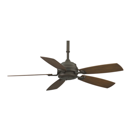
Standard Fan
Net Weight 12.93 kg
(28.5 lbs)
WARNING: Support Directly From Building Structure
Models No. HF6050, 6200, 6600 Series
OWNER'S MANUAL
READ AND SAVE THESE INSTRUCTIONS
H
UBBARDTON
For Canada, this fan must be secured directly to the building structure or ceiling joist.
Don't secure this fan to an outlet box.
Standard
Presidio Tryne
Net Weight 14.51 kg
(32 lbs)
F
D
, M
ORGE
ESIGN
ANUFACTURED AND
™
Fan
D
B
ISTRIBUTED
Y
Standard Leaf Fan
Net Weight 14.51 kg
(32 lbs)
F
ANIMATION
Advertisement
Table of Contents

Related Manuals for Fanimation HF6050 Series


Summary of Contents for Fanimation HF6050 Series
- Page 1 Standard Fan Net Weight 12.93 kg (28.5 lbs) WARNING: Support Directly From Building Structure Models No. HF6050, 6200, 6600 Series OWNER’S MANUAL READ AND SAVE THESE INSTRUCTIONS UBBARDTON ORGE For Canada, this fan must be secured directly to the building structure or ceiling joist.
-
Page 2: Table Of Contents
Fanimation. 7. Fanimation reserves the right to modify or discontinue any product at any time and may substitute any part under this warranty. 8. Under no circumstances may a fan be returned without prior authorization from Fanimation. The receipt of purchase must ac- company authorized returns and must be sent freight prepaid to Fanimation. -
Page 3: Tools Needed For Assembly
Fanimation. Substitution of parts or accessories not designated for use with this product by Fanimation could result in personal injury or property damage. Contact your retail store for missing or damaged parts. -
Page 4: Electrical And Structural Requirements
Electrical and Structural Requirements Your new ceiling fan will require a grounded electrical supply line of 120 volts AC, 60 Hz, 15 amp circuit. The outlet box must be securely anchored and capable of withstanding a load of at least 22.7 kgs (50 lbs). Figure 1 depicts different structural configurations that may be used for mounting the outlet box. - Page 5 How to Assemble Your Down Rod Sleeve (cont’d) 12˝ Down Rod Assembly: 3. Assemble two Collars and 4˝ Sleeve, as shown (Figure 3). 18˝ Down Rod Assembly: 4. Assemble the 18˝ Down Rod and the Sleeve Kit in the order as shown (Figure 4). 24˝...
-
Page 6: How To Assemble Your Ceiling Fan
How to Assemble Your Ceiling Fan 1. Prior to assembly, set aside and save the hardware bag(s) packed in the packing. 2. Remove the Hanger Ball by loosening the setscrew in the Hanger Ball until the ball falls freely down the Downrod. - Page 7 How to Assemble Your Ceiling Fan (cont’d) 8. Route wires & cable through opening in Canopy. Position Canopy on fan shown with open side facing up. (Figure 4) 9. Reinstall the Hanger Ball (Figure 3) on the Downrod as follows. Route the three 80˝ wires through the Hanger Ball.
-
Page 8: How To Hang Your Ceiling Fan
How to Hang Your Ceiling Fan ▲WARNING To avoid possible electrical shock, be sure electricity is turned off at the main fuse box before hanging. NOTE: If you are not sure if the outlet box is grounded, contact a licensed electrician for advice, as it must be grounded for safe operation. -
Page 9: How To Wire Your Ceiling Fan - C20 Remote Control
How to Wire Your Ceiling Fan - C20 Remote Control If you feel that you do not have enough electrical wiring knowledge or experience, have your fan installed by a licensed electrician. NOTE: If fan or supply wires are different colors than indicated, have this unit installed by a qualifi... -
Page 10: Installing The Canopy Housing
Installing the Canopy Housing NOTE: This step is applicable after the necessary wiring is completed. (see page 9) ▲WARNING To avoid possible fire or shock, make sure that the electrical wires are completely inside the canopy housing and not pinched between the housing and the ceiling. 1. -
Page 11: Installing The Receiver Unit And Switch Cup Housing
Installing the Receiver Unit and Switch Cup Housing NOTE: This step is applicable for model without lower Light Kits. For Forged Leaf or Presidio Tryne section and go to page 14 or 16. 1. Install receiver unit in the switch cup cover by align the two green dots. -
Page 12: Parts List
Ref. # Standard Fan Assembly Leaf Fan Assembly (for LK info, see pages 14 & 15) Presidio Tryne™ Fan Assembly (for LK info, see pages 16 & 17) STANDARD FAN ASSEMBLY — HF6050** Hanger Bracket Assembly Ball/Downrod Assembly Downrod Cover Assembly... -
Page 13: Exploded-View Drawing
Standard Fan HF6050** Exploded-View (also for Leaf & Presidio Tryne™ Fans) Figure 1 NOTE: The illustration shown is not to scale or its actual confi guration may vary... -
Page 14: Installing The Leaf Light Kit - Lkhf7260
Installing the Leaf Light Kit – LKHF7260** Leaf Fan Model: CAUTION To avoid possible electrical shock, be sure electricity is turned off at the main fuse box before installing light kit. Figure 1 1. Remove the plug, lockwasher and nut from the bottom of switch cup cover. -
Page 15: Leaf Light Kit - Lkhf7260** - Parts Identifi Cation
60 watt candelabra bulbs (not included). Leaf Light Kit – LKHF7260** — Parts Identifi cation LEAF FAN ASS’Y – HF7200BZ • HF6050** - Fan Motor Asm/Blades • LKHF7260** - Downlight Stone Glass Bowl Leaf Down Light Kit Parts List - LKHF7260**... -
Page 16: Installing The Presidio Tryne™ Light Kit - Lkhf7660
Installing the Presidio Tryne Presidio Tryne Fan Model: ™ CAUTION To avoid possible electrical shock, be sure electricity is turned off at the main fuse box before installing light kit. Figure 1 1. Remove the plug, lockwasher and nut from the bottom of switch cup cover. -
Page 17: Presidio Tryne™ Light Kit - Lkhf7660** - Parts Identifi Cation
60 watt candelabra bulbs (not included). Presidio Tryne ™ PRESIDIO TRYNE FAN ASS’Y – HF7600** ™ • HF6050** - Fan Motor Asm/Blades • LKHF7660DS - Downlight Stone Glass Bowl Presidio Tryne Down Light Kit ™ Parts List - LKHF7660**... -
Page 18: Trouble Shooting
For your own safety turn off power at fuse box or circuit breaker before trouble shooting your fan. Trouble 1. Fuse or circuit breaker blown. 2. Loose power line connections to the fan, or loose switch wire connections in the switch housing. 1. - Page 20 Zionsville, IN 46077 (888) 567-2055 FAX (866) 482-5215 Outside U.S. call (317) 733-4113 Visit Our Website www.fanimation.com Copyright 2008 Fanimation 2008/01 All Hubbardton Forge designs, the mark HUBBARDTON FORGE and the design of the tongs are trademarks or registered trademarks of Hubbardton Forge Corporation.