
Related Manuals for Atlanta 1347MGB


Summary of Contents for Atlanta 1347MGB
- Page 1 1347MGB Model Revision 1.3 Updated Jun 7, 2016 Technical Manual & Parts Lists Atlanta Attachment Company 362 Industrial Park Drive Lawrenceville, GA 30046 770-963-7369 • www.atlatt.com...
- Page 3 Attachment Company. In addition to any confidentiality and non-disclosure obligations that currently exist between you and Atlanta Attachment Company, your use of these materials serves as an acknowledgment of the confidential and proprietary nature of these materials and your duty not to make any unauthorized use or disclosure of these materials.
-
Page 4: Table Of Contents
Technical Manual & Parts Lists Contents Important Safety Instruction ........................1 Liability ..............................2 Safety Equipment on the Machines ......................3 Protective Eyewear ............................. 4 Important Notices............................5 Maintenance ..............................7 Repair ................................8 A Word to the End User..........................9 Safety Precautions ............................ -
Page 5: Important Safety Instruction
Mandatory Information All persons operating and/or working on the 1347MGB Auto Dual Binder should read and understand all parts of the Safety Instructions. This applies, in particular, for persons who only operate and/or work on the unit occasionally (e.g. for maintenance and repair). Persons who have difficulty reading must receive particularly thorough instruction. -
Page 6: Liability
Technical Manual & Parts Lists Liability The machine should only be operated when in perfect working order, with due regard for safety and the potential dangers, as well as in accordance with the Instruction Material. Faults and malfunctions capable of impairing safety should be remedied immediately. We cannot accept any liability for personal injury or property damage due to operator errors or non-compliance with the safety instructions contained in this booklet. -
Page 7: Safety Equipment On The Machines
Technical Manual & Parts Lists A Word to the Operator The greatest danger inherent in our machines: is that of fingers, hands or loose clothing being drawn into a machine by live, coasting or rotating tools or assemblies or of being cut by sharp tools or burned by hot elements. LWAYS BE CONSCIOUS OF THESE DANGERS Safety Equipment on the Machines All machines are delivered with safety equipment, which shall not be removed or... -
Page 8: Protective Eyewear
Technical Manual & Parts Lists Protective Eyewear Protective eyewear that has been tested by the local authorities should be worn whenever there is a possibility of loose or flying objects or particles such as when cleaning the machine with compressed air. Tools Always count the number of tools in your possession before starting work on the machine. -
Page 9: Important Notices
Technical Manual & Parts Lists Important Notices Reporting and Fighting Fires Read the instructions posted in the factory with regard to reporting fires and the emergency exits. Make sure you know exactly where the fire extinguishers and sprinkler systems are located and how they are operated. - Page 10 The packaging and machine must immediately be examined for signs of damage in transit. Such damage must be reported to the shipper/transporter within the applicable time limits. Contact Atlanta Attachment Company and/or your transport insurer immediately, if signs of damage are visible. Never operate a damaged machine.
-
Page 11: Maintenance
Technical Manual & Parts Lists Protect against influences from the surroundings: no structure-borne vibrations, no grinding dust, or chemical vapors. Protect against unauthorized access. Ensure that the machine and accessories are set up in a stable position. Ensure easy access for operation and maintenance (Instruction Manual and layout diagram); also verify that the floor is strong enough to carry the weight of the machine. -
Page 12: Repair
Technical Manual & Parts Lists Repair Replacement Parts We cannot accept any liability whatsoever for damage due to the use of parts made by other manufacturers or due to unqualified repair or modification of the machine. Repair, Electrical The power supply must be switched off (master switch off) and secured so that it cannot be switched on again inadvertently before starting any work on live parts. -
Page 13: A Word To The End User
Technical Manual & Parts Lists Read the Instruction Manual carefully to establish which keys and functions start machine movements. A Word to the End User The end user has sole responsibility to enforce the use of safety procedures and guards on the machine. Any other safety devices or procedures due to local regulations should be should be retrofitted in accordance to these regulations and/or the EC Directive on the safety of machines. -
Page 14: Component Identification
Technical Manual & Parts Lists Component Identification... -
Page 15: Operating Instructions
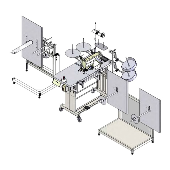
Technical Manual & Parts Lists This machine should include a set of roll holders for the border, tape and cording materials, a sewing console, and an electro-pneumatic rewinder. The border roll holders have a set of sensors that will stop the machine when the materials run out. -
Page 16: Electric Eye Sensor
Technical Manual & Parts Lists Electric Eye Sensor Mount the sensor so that it is 2-6” from the material to be detected. The sensor does not have to be perpendicular to the material. An angle of up to 30 degrees can be used. Operation The green LED indicates power on. -
Page 17: Assembly Drawings & Parts Lists
Company. In addition to any confidentiality and non-disclosure obligations that currently exist between you and Atlanta Attachment Company, your use of these materials serves as an acknowledgment of the confidential and proprietary nature of these materials and your duty not to make any unauthorized use or... - Page 18 Technical Manual & Parts Lists...
-
Page 19: 11347Mgb Auto Dual Binder
Technical Manual & Parts Lists 11347MGB Auto Dual Binder AAC Drawing Number 9002720 Rev 0 QTY PART # DESCRIPTION Page 17 1330200 REWINDER W/MOUNTING ASSY Page 1347475 GUARD, MOTOR BELT 1347536 MATERIAL EDGE GUIDE Page 21 1347537 WORK STATION,DUAL BNDR Page Page 29 1347544... - Page 20 Technical Manual & Parts Lists...
-
Page 21: 1330200 Rewinder W/ Mounting Assembly
Technical Manual & Parts Lists 1330200 Rewinder W/ Mounting Assembly AAC Drawing Number 1330200 Rev 4... - Page 22 Technical Manual & Parts Lists...
-
Page 23: 1347098 Rewind Assembly W/ Sleeve
Technical Manual & Parts Lists 1347098 Rewind Assembly W/ Sleeve AAC Drawing Number 1347098 Rev 1 NO. QTY PART# DESCRIPTION NO. QTY PART# DESCRIPTION 1961-319 PLATE,NUT,3/8-16@3.00 NNH1/2-13 NUT,HEX,1/2-13 1961-321 PLATE, ADAPTOR, AIR NNH3/8-16 NUT,HEX,3/8-16 1961-331 MOUNT, MOTOR NNK1/4-20 NUT,HEX,KEP,1/4-20 1961-332 COVER, MOTOR PP22LB075-1-1/8 PULLEY, GEAR, 3/8P... - Page 24 Technical Manual & Parts Lists...
-
Page 25: 1347537 Work Station
Page 1347567 DBL BINDING GUIDE 1347570 BRKT,SWING OUT Page 25 1347580 SEWING HEAD ASSBLY Page Page 26 1347586 TENSION RACK, 1347MGB Page 1349304 ROD,STRA,CRS,1/2 X 33 1959-112 2 POS THREAD PLATE ASSY 1975-412A PLATE,NUT,4-40,.95CTC 213-005Y PUSH BUTTON ASSY,YELLOW 26151 TOOL TRAY, 1X3.5X9... - Page 26 Technical Manual & Parts Lists...
-
Page 27: 1347329 Table & Stand Assembly
Technical Manual & Parts Lists 1347329 Table & Stand Assembly AAC Drawing Number 1347329 Rev 3 NO. QTY PART# DESCRIPTION PART# DESCRIPTION 4000D-500 CONTROL BOX NNE10-32 NUT,ELASTIC LOCK *AR 0411-069C BRKT, THREAD NNH5/16-18 5/16-18 HEX NUT *AR 0411-070 CLAMP, SENSOR NNJ1/4-28 NUT, HEX, JAM, 1/4-28 1959-120... -
Page 28: 1347560 Dual Binder Assembly
Technical Manual & Parts Lists 1347560 Dual Binder Assembly AAC Drawing Number 1347560 Rev 0 QTY PART # DESCRIPTION 1347561 MOUNT,BLOCK BINDER 1347562 SPACER, 1/4",BINDER BLK AR 1347565 CORD GUIDE ASBLY, DUAL 1/4" AR 221-092016D1 BLOCK BINDER,1-7/16 X 1/4 SSPS98056 #10-32X 7/8 PAN HD SLTD WWFS10 WASHER, FLAT, #10, SAE... -
Page 29: 1347580 Sewing Head Assembly
Technical Manual & Parts Lists 1347580 Sewing Head Assembly AAC Drawing Number 1347580 Rev 1 NO. QTY PART # DESCRIPTION NO. QTY PART # DESCRIPTION 11200A BUMPER 5/16-24 AAF4568K116 NIPPLE,1/4NPT X 3.5L 1335-109 ADAPTER,DRAIN PLUG AAQME-5-8 QUICK MALE ELBOW 1335-111 BRKT,CYLINDER M1Y88-003 FOOT, SN, 1335MG... -
Page 30: 1347586 Tension Rack
Technical Manual & Parts Lists 1347586 Tension Rack AAC Drawing Number 1347586 Rev 1 QTY PART # DESCRIPTION 1344015 PLATE, EDGE GUIDE 1347583 MOUNT,GUIDE,LEFT 1347585 MOUNT,GUIDE,RIGHT 1961-206A ROD, MATERIAL TENSION SSHC10048 5/16-18 X 3/4 HHCS TTH32415 HANDLE,THREADED,1/4-20X7/ WWF5/16 WASHER,FLAT,5/16 WWL5/16 WASHER, LOCK, 5/16... -
Page 31: 1961-210B Tension Rack Assembly
Technical Manual & Parts Lists 1961-210B Tension Rack Assembly AAC Drawing Number 9001739 Rev 1 QTY PART # DESCRIPTION 1961-206A ROD, MATERIAL TENSION 1961-207 PLATE, END 1961-211 PLATE, EDGE GUIDE 1961-403A SUPPORT, GUIDE SSAS024064 3/8 X 1 X 5/16-18 SHLD, BOLT SSHC10048 5/16-18 X 3/4 HHCS TTH32415... - Page 32 Technical Manual & Parts Lists...
-
Page 33: 1347544 Dual Roll Holder Assembly
Technical Manual & Parts Lists 1347544 Dual Roll Holder Assembly AAC Drawing Number 1347544 Rev 0 PART# DESCRIPTION 784B-2432 PLATE, ALU 1961-204 ROLLER,15.5L,2 OD,.75 ID 1961-251C HUB UNWIND SHAFT 1961-253A HUB, UNWIND STAND 1961-255 BRACKET, SENSOR MTG 1962-3201 CLAMP,3/4ROD,3"CTC 28201 BLOCK,CROSS,(LARGE) 1347436 ROD, BENT, 90 DEG... -
Page 34: 33008708 Ball Bearing Disc Assembly
Technical Manual & Parts Lists 33008708 Ball Bearing Disc Assembly AAC Drawing Number 9000904 Rev 4 PART# DESCRIPTION 33008604 CONE, SPOOL 33008602 HUB, FLANGE 3/4 BORE SEE CHART SEE CHART 33008601 HUB, CENTER, 3/4 SHAFT BB23216-88 BEARING,BALL,1.0B RRLC026B1 SPRING,COMP .026X.18X.25 JJ012 3/16"... -
Page 35: 4000D-500 Control Box, 4000D
Technical Manual & Parts Lists 4000D-500 CONTROL BOX, 4000D AAC Drawing Number 9005195 Rev 1 NO QTY PART # DESCRIPTION NO QTY PART # DESCRIPTION 4000D-01 BOX BOTTOM,PLAIN FF342838A FUSE HOLDER, PANEL MOUNT 4000D-02 PC BOARD, RELAY FF700-FEA3TU23 RELAY,TIMER,DIN,ON DELAY 4000D-WD4 WIRING DIAGRAM, W/TIMER FFGFTS-4... -
Page 36: 1347Ma-Pd Pneumatic Diagram
Technical Manual & Parts Lists 1347MA-PD Pneumatic Diagram 125296B... -
Page 37: 1347Ma-Wd Wiring Diagram
Technical Manual & Parts Lists 1347MA-WD Wiring Diagram 125297B... - Page 38 Atlanta Attachment Company (AAC) Statement of Warranty Manufactured Products Atlanta Attachment Company warrants manufactured products to be free from defects in material and workmanship for a period of eight hundred (800) hours of operation or one hundred (100) days whichever comes first. Atlanta Attachment Company warrants all electrical components of the Serial Bus System to be free from defects in material or workmanship for a period of thirty six (36) months.
- Page 39 Declaración de Garantía Productos Manufacturados Atlanta Attachment Company garantiza que los productos de fabricación son libres de defectos de material y de mano de obra durante un período de ochocientos (800) horas de operación o cien (100) días, cual llegue primero.
- Page 40 Atlanta Attachment Company 362 Industrial Park Drive Lawrenceville, GA 30046 770-963-7369 www.atlatt.com Printed in the USA...
Need help?
Do you have a question about the 1347MGB and is the answer not in the manual?
Questions and answers