
Related Manuals for Atlanta 4500A


Summary of Contents for Atlanta 4500A
- Page 1 Model 4500A Rev 1.6 Updated Jan 23, 2017 Technical Manual & Parts Lists Atlanta Attachment Company 362 Industrial Park Drive Lawrenceville, GA 30046 770-963-7369 • www.atlatt.com...
- Page 3 Attachment Company. In addition to any confidentiality and non-disclosure obligations that currently exist between you and Atlanta Attachment Company, your use of these materials serves as an acknowledgment of the confidential and proprietary nature of these materials and your duty not to make any unauthorized use or disclosure of these materials.
-
Page 4: Table Of Contents
Technical Manual & Parts Lists Contents Important Safety Instruction ........................1 Liability ..............................2 Safety Equipment on the Machines ......................3 Protective Eyewear ............................. 4 Important Notices............................5 Maintenance ..............................7 Repair ................................8 A Word to the End User..........................9 Safety Precautions ............................ - Page 5 Technical Manual & Parts Lists 2.3. Operating Sequences .......................... 51 2.3.1 Standard Operating Sequences ......................52 2.3.2 Changing the Needle on Sew Head 1 & 2 ..................55 2.3.3 Threading Sew Head 1 & 2 ......................56 2.3.4. Needle ............................. 57 2.3.5 Looper ..............................
- Page 6 3.6. EFKA Parameters ..........................91 3.6.1.- Efka Box Error Codes........................91 Cable support installation (84”) ......................92 Assembly Drawings & Parts Lists ......................95 4500A ................................ 96 1312128 Thread Stand Assembly ......................97 1312122 Thread Stand Needles ........................ 98 4500347 Pre-Tension Assembly ....................... 99 4500316 Stop/Jog/Stop Button Assembly ....................
- Page 7 1388986 Touchscreen Assembly ......................144 4500902 Backplane, Back Side Assembly ..................... 145 4500904 Backplane, Front Side Assembly ..................... 146 4500A-PD Pneumatic Diagram ......................147 4500-WD3 Wiring Diagram, Pattern Sew PLC, I/O ................148 4500-WD4 Wiring Diagram, Main Cabinet ................... 149 4500-WD5 Wiring Diagram, Pattern Sew SOL ..................
- Page 8 Technical Manual & Parts Lists Signal Word! (Characterizes the severity of the danger) Note (describes the danger and informs how to proceed) Hazard warning sign: General Hand hazard sign or symbol Hazard Hazard warning sign: Electrical Designates a general, useful note. hazard, electrical hazard...
-
Page 9: Important Safety Instruction
Technical Manual & Parts Lists Important Safety Instruction This part of the Instruction Material is provided for the safe use of your equipment. It contains important information to help work safely with the unit and describes the dangers inherent in machinery. Some of these dangers are obvious, while others are less evident. -
Page 10: Liability
Technical Manual & Parts Lists Liability The machine should only be operated when in perfect working order, with due regard for safety and the potential dangers, as well as in accordance with the Instruction Material. Faults and malfunctions capable of impairing safety should be remedied immediately. We cannot accept any liability for personal injury or property damage due to operator errors or non-compliance with the safety instructions contained in this booklet. -
Page 11: Safety Equipment On The Machines
Technical Manual & Parts Lists A Word to the Operator The greatest danger inherent in our machines: is that of fingers, hands or loose clothing being drawn into a machine by live, coasting or rotating tools or assemblies or of being cut by sharp tools or burned by hot elements. LWAYS BE CONSCIOUS OF THESE DANGERS Safety Equipment on the Machines All machines are delivered with safety equipment, which shall not be removed or... -
Page 12: Protective Eyewear
Technical Manual & Parts Lists Protective Eyewear Protective eyewear that has been tested by the local authorities should be worn whenever there is a possibility of loose or flying objects or particles such as when cleaning the machine with compressed air. Tools Always count the number of tools in your possession before starting work on the machine. -
Page 13: Important Notices
Technical Manual & Parts Lists Important Notices Reporting and Fighting Fires Read the instructions posted in the factory with regard to reporting fires and the emergency exits. Make sure you know exactly where the fire extinguishers and sprinkler systems are located and how they are operated. - Page 14 The packaging and machine must immediately be examined for signs of damage in transit. Such damage must be reported to the shipper/transporter within the applicable time limits. Contact Atlanta Attachment Company and/or your transport insurer immediately, if signs of damage are visible. Never operate a damaged machine.
-
Page 15: Maintenance
Technical Manual & Parts Lists Protect against influences from the surroundings: no structure-borne vibrations, no grinding dust, or chemical vapors. Protect against unauthorized access. Ensure that the machine and accessories are set up in a stable position. Ensure easy access for operation and maintenance (Instruction Manual and layout diagram); also verify that the floor is strong enough to carry the weight of the machine. -
Page 16: Repair
Technical Manual & Parts Lists Repair Replacement Parts We cannot accept any liability whatsoever for damage due to the use of parts made by other manufacturers or due to unqualified repair or modification of the machine. Repair, Electrical The power supply must be switched off (master switch off) and secured so that it cannot be switched on again inadvertently before starting any work on live parts. -
Page 17: A Word To The End User
Technical Manual & Parts Lists A Word to the End User The end user has sole responsibility to enforce the use of safety procedures and guards on the machine. Any other safety devices or procedures due to local regulations should be should be retrofitted in accordance to these regulations and/or the EC Directive on the safety of machines. -
Page 18: Installation Manual
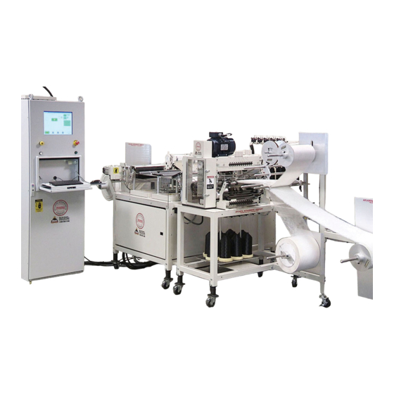
Technical Manual & Parts Lists 1. INSTALLATION MANUAL It is important that the machine operator read this manual and is familiar with all the functions and safety concerns of the unit before operating. 1.1. Parts and Components 1.- Material Roll Holder 2.- Multi-needle Quilter 3.- Sew Head 1 4.- Sew Head 2... -
Page 19: Technical Data
Technical Manual & Parts Lists 1.2. Technical Data Max Speed (sew heads 1 & 2) 3000 rpm Factory Preset Speed (sew heads 1 & 2) 2400 rpm Multi-needle quilter Max Speed 1200 rpm Max Border Width (finished) 18” Weight of Material Light/Medium Max Stitch Length 5 spi... -
Page 20: Installation & Set Up
Technical Manual & Parts Lists 1.3. Installation & Set Up It is important that the machine operator read this manual and is familiar with all the functions and safety concerns of the unit before installing or operating. 1. Unpack the machine frame and install it with help of a suitably rated fork truck. (Suitably rated long forks or straps may be required for proper installation.). -
Page 21: Lockout/Tagout Procedures
The following references provide information about the LOTO process. Equipment Energy Control Procedure Lockout/Tagout Program Description: Border Quilter Model: 4500 Single Lane Border Quilter Manufacturer: Atlanta Attachment Co. Location: Energy Location Magnitude Control Method Electrical: Disconnect/Ctrl Box 220 VAC Lockout &... -
Page 22: Operation Manual
Technical Manual & Parts Lists 2. OPERATION MANUAL It is important that the machine operator read this manual and is familiar with all the functions and safety concerns of the unit before operating 2.1 System components The machine consists of the following major sections ... -
Page 23: Multi-Needle Quilter
Technical Manual & Parts Lists 2.1.2 Multi-needle Quilter Located after the Material Roll Holder, the Multi-needle Quilter is a straight line chain stitch machine. The quilter has a quarter inch needle spacing and adjustable loopers, too allow for a great variety of patterns to be utilized. -
Page 24: Material Puller
Technical Manual & Parts Lists 2.1.4 Material Puller Located after Sew Head 1 and 2, the Puller moves the material from the Multi-needle Quilter under the guide rollers and Sew Heads. The puller speed will vary greatly depending on the selected pattern. The Puller is servo driven to maintain the integrity of the selected pattern. -
Page 25: Control Cabinet
Technical Manual & Parts Lists 2.1.6 Control Cabinet a. Main Power Disconnect Located on the right side of the Main Control panel, this is the main power switch. Rotating ¼ turn to the right will supply power to the machine. This switch has provision to lockout the power when performing maintenance. - Page 26 Technical Manual & Parts Lists e. Pneumatic Air Cutoff A single Red knob located at the Air Supply Regulator; twisting this knob ¼ turn left releases air pressure from the system components. This valve has provision to lockout the air supply when performing maintenance.
-
Page 27: Touch Screen Controls
Technical Manual & Parts Lists 2.2. Touch Screen Controls 2.2.1 Touch Screen Navigation Tree Main Operator Screen View Status Load Pattern Pattern Settings Input/Output Control Technician... -
Page 28: Touch Screen Finger Pad Colors
Technical Manual & Parts Lists 2.2.2 Touch Screen Finger Pad Colors The 4500 Machine Control Touch Screen software uses colored finger pads to guide the operator in selecting control buttons. YELLOW finger pads o Cause the machine to move or change data parameters – please observe caution. - Page 29 Technical Manual & Parts Lists Stopped Error Reset Restart Activate Solenoids Manual Idle Enable Motors Tech Settings Homing Manual Mode Load Pattern Go to Park At Park Manual Ready Auto Mode Auto Ready Enable Pattern Running Disable Pattern...
-
Page 30: Main Operator Screen
Technical Manual & Parts Lists 2.2.4 Main Operator Screen This is the Main Operator screen and is displayed at the startup of the machine. The screen is divided into three (3) frames and has a bottom row of navigation and control buttons. - Page 31 Technical Manual & Parts Lists The Operator Menu frames are: a. Machine Setup Frame Under setup displays the operator’s basic machine control buttons. Buttons are normally colored GRAY. When a button is activated, the button will turn GREEN. If a fault occurs, then the button will turn RED.
- Page 32 Technical Manual & Parts Lists Note: This buttons are only visible when the machine is placed in “MANUAL” mode 1. Home All Pressing the button will automatically move the Y01 and Y02 sew heads forward to search for the Home proximity sensor. Once the sensor is detected, the sew heads then move back to the Home Offset Position.
- Page 33 Technical Manual & Parts Lists b. Pattern Frame Figure 2.2.4b Operator Pattern Control This frame groups the Pattern Control buttons. 1.- Load Pattern Pressing this button will display the “Load Pattern” screen described in section 2.2.6 Note: This button is only visible when the machine is placed in “MANUAL” mode 2.- Enable Pattern Note: Before pressing this button: ...
- Page 34 Technical Manual & Parts Lists c. Machine Status Frame This frame displays a real time representation of the machine status. The various control devices and sensors are displayed in different colors to assist the operator and maintenance technician to quickly identify correct operation.
- Page 35 Technical Manual & Parts Lists Rewind Enabled Puller Enabled Sew Head Quilter Enabled Enabled Figure 2.2.4.d1 System Enabled Areas...
- Page 36 Technical Manual & Parts Lists Pressure Pause Button Restart Button Dancer Up Safety Position Relay Quilter Needle Up 1/2 Thread Break Q Thread Material Break Figure 2.2.4.d2 Sensor Positions corresponding to Machine Status...
- Page 37 Technical Manual & Parts Lists d. Operator Screen Automatic / Manual Status The Machine Mode may only be selected from the touchscreen. 1. Touchscreen Manual Mode Selection The operator may place the machine into Manual mode by clicking the Automatic / Manual button located on the OPERATOR’S SCREEN until the arrow points down towards the words “Manual”...
- Page 38 Technical Manual & Parts Lists 1. Enable Motion This is the global Machine Motion Enable button and will generally be used to permit motion to all motors or air cylinders. When this button is activated, the operator may begin all other machine functions such as Homing or Pattern movements When the operator presses this button, a software signal is sent to the controller indicating that the operator wishes to enable motion.
-
Page 39: View Status Screen
Technical Manual & Parts Lists 2.2.5 View Status Screen Pushing the status button allows the operator to view the machine speeds and the actual position of the pattern profile. Needle Sew Head 01 (-02) This dial indicates the actual Sew Head speed in units of Stitches per Minute Puller Dial... -
Page 40: Load Pattern File Screen
File Dialog box that displays the file directory in the hard drive where the operator has stored the pattern files that were created using Atlanta Attachment’s EZ Pattern Design software. The File Dialog Box waits until the operator selects a file directory for viewing. - Page 41 Technical Manual & Parts Lists No File Reset Loaded Install Pattern Select Material Errors? Errors Read Error Parsing Error No Errors Loading Error CNC File Ready...
-
Page 42: Pattern Settings Screen
Technical Manual & Parts Lists 2.2.7 Pattern Settings Screen Path Speed This screen allows the operator to adjust pattern parameters. This parameter overrides the virtual Master axis path speed setting that is Sew Head Speeds calculated based on the Each Sew Head has a pattern shape. -
Page 43: Pattern Settings Details
Technical Manual & Parts Lists 2.2.8 Pattern Settings Details This section describes the pattern SCALE, OFFSET and SHIFT control functions in more detail The patterns are developed using an imaginary X-axis line that runs along the direction of the PULLER and an imaginary Y-axis line that runs in the direction of the SEW HEADS The X-axis and the Y-axis intersect at the Y-HomeOffset Position, which has been factory set for the center of the quilter. - Page 44 Technical Manual & Parts Lists a. Pattern Design Patterns are designed using Atlanta Attachment’s E-Z Pattern Designer software. The patterns are then loaded into the machine controller from the LOAD PATTERN Screen by selecting a pattern using the “View CNC File” button ...
- Page 45 Technical Manual & Parts Lists b. SCALE Pattern The size of the pattern may be changed by either: Moving the SCALE Trackbar slider or if more precision is required, by clicking the gray SCALE icon and manually entering a value using the Parameter Entry Keypad.
- Page 46 Technical Manual & Parts Lists c. OFFSET Pattern The pattern may be moved up or down the Y-axis by either : Moving the OFFSET Trackbar slider or if more precision is required, by clicking the gray OFFSET icon and manually entering a value using the Parameter Entry Keypad.
- Page 47 Technical Manual & Parts Lists d. SHIFT Pattern The pattern may be moved along the X-axis by either : Moving the SHIFT Trackbar slider or if more precision is required, by clicking the gray SHIFT icon and manually entering a value using the Parameter Entry Keypad.
-
Page 48: Input / Output Menu Screen
Technical Manual & Parts Lists 2.2.9 Input / Output Menu Screen This screen is a menu screen that allows the technician to operate the machine’s Input and Output Control screens as described below. The screen is divided into four frames: Solenoids, Enable Motors, Machine Status and Command. - Page 49 Technical Manual & Parts Lists a. Solenoid Control: These buttons are normally GRAY in color to indicate that the solenoids are not active. The button changes to GREEN color when the solenoid valve is active and RED if the system detects a fault. Each valve may be activated by clicking its corresponding button.
- Page 50 Technical Manual & Parts Lists b. Enable Motors: This group of buttons will allow the individual motors to turn ON or Each motor may be activated by clicking on its corresponding button. The button will turn GREEN when the system allows the motor to function.
- Page 51 Technical Manual & Parts Lists c. Machine Status: This frame displays a real time representation of the machine status. The various control devices and sensors are displayed in different colors to assist the operator and maintenance technician to quickly identify correct operation. The colors indicate various machine states and in general are as follows: ...
-
Page 52: Technician Screen
Technical Manual & Parts Lists 2.2.10 Technician Screen This screen allows the operator to adjust basic system parameters. CAUTION Changing these parameters may cause damage to the needle/looper mechanism or loss of communication to the controller. The qualified technician may change parameters only while the machine is in MANUAL mode and not producing. - Page 53 Technical Manual & Parts Lists c. Stitch Length: This parameter sets the stitch length [millimeters] for internal calculations. d. Thread Break Delay: This parameter delays the Thread Break sensor from causing an alarm. The units are in 100 millisecond increments. For example; a setting of 7 means that the system will delay 700 milliseconds before pausing the machine on a thread break.
-
Page 54: Parameter Entry Screen
Technical Manual & Parts Lists 2.2.11 Parameter Entry Screen This is the general purpose numeric entry screen for system parameters. The dial indicates the current setting and the parameters’ minimum and maximum values that may be entered. A small text box below the dial explains the parameters function. Figure 2.2.11 a. -
Page 55: Password Screen
Technical Manual & Parts Lists 2.2.12 Password Screen This is the numeric entry screen for password enabled functions. Figure 2.2.12 a. Clear button “C” This softbutton will clear any number in the display area b. Numbers 0-9 These softbuttons may be pressed to form a number in the display. c. -
Page 56: Error Messages
Technical Manual & Parts Lists 2.2.13 Error Messages The system will trigger a message box to alert the operator of abnormal conditions. The list below displays the various types of messages the operator may observe. The message box will have buttons to guide the operator to clear the fault and resume operation. - Page 57 Technical Manual & Parts Lists Efka Drive Fault o Efka Motor Drive Fault A fault was detected on the Efka drive. Notify a technician and verify the cause of the drive fault. Clear the fault by pressing the Emergency Stop button to disable the Quilter motor and gently move the Quilter motor pulley to verify that there is no mechanical jam.
- Page 58 Technical Manual & Parts Lists c. Pattern File Faults File Read Error The pattern file could not be read from the PC hard drive. Retry or select a new file. File Parsing Error The pattern file could was read correctly but the information was not correct for the 4500 machine.
-
Page 59: Operating Sequences
Technical Manual & Parts Lists 2.3. Operating Sequences It is important that the machine operator read this manual and is familiar with all the functions and safety concerns of the unit before operating “ATTENTION: Never leave the machine unattended while power is ON” The machine is normally operated using a standard sequence of operations. -
Page 60: Standard Operating Sequences
4.- Launch Software icon Click the AAC 4500 Machine Control icon on the desktop to launch the software. The machine will show Atlanta Attachment logo followed by the Main Operator’s Screen after a few seconds. 5.- Motion Enable softbutton Click the “Motion Enable” softbutton located on the lower left of the Main Operator’s Screen. This will activate the servo power control relays. - Page 61 Technical Manual & Parts Lists b. Homing the Machine ID Location Device Action Operator Screen Home All softbutton Click Main Screen Machine Status: Homing Wait Main Screen Machine Status: Ready 1.- Home All softbutton Click the “Home All” softbutton located on the top left corner of the operator’s screen.
- Page 62 Technical Manual & Parts Lists d. Selecting a Pattern File ID Location Device Action Main Screen Load Pattern softbutton Click Load Pattern Screen View CNC File softbutton Click Pattern Setting Screen Install Pattern softbutton Click 1.- Load Pattern button With the machine ON and HOMED – click the “Load Pattern” button on the Main Menu to navigate to the Load Pattern Screen 2.-View CNC File button Click the “View CNC File”...
-
Page 63: Changing The Needle On Sew Head 1 & 2
Technical Manual & Parts Lists 2.3.2 Changing the Needle on Sew Head 1 & 2 Please follow all safety procedures, turning the power off to the machine is recommended. Locate the slotted needle screw, located on the left side of the needle chuck. Insert a small flat blade screw drive through loosens the screw. -
Page 64: Threading Sew Head 1 & 2
Technical Manual & Parts Lists 2.3.3 Threading Sew Head 1 & 2 Please follow all safety procedures, turning off power is recommended. Thread is routed through the sensor and then into a tube that ends near the rear of the sew head above the carriage. -
Page 65: Needle
Technical Manual & Parts Lists 2.3.4. Needle With the needle bar raised to its highest position, pass the thread in order as show in the picture 1.- Pass the thread hole toward to opposite side of the operator from the operator side. 2.- Pull out the thread which was passed through the needle about 10 cm (4”) 2.3.5 Looper... -
Page 66: Threading Multi-Needle Quilter
Technical Manual & Parts Lists 2.3.6 Threading Multi-needle Quilter Needle threads are located to the right of the Multi-needle Quilter, while the Looper threads are located on the thread stand next to the needle thread stand. Thread is routed through the sensors and tension disks. -
Page 67: Loading Material
Technical Manual & Parts Lists 2.3.7 Loading Material Please follow all safety procedures, turning off power is recommended. Follow Pictures for details. -
Page 68: Sewing Procedure
Technical Manual & Parts Lists 2.3.8 Sewing Procedure Please follow all safety procedures, turning off power is recommended. Check that each sewing head is locked into its respective carriage. The two threaded knobs in the connector plate on the right side of each carriage; locks the head to the carriage. Removing the knobs allows the heads to be pulled to the extreme right in order to tilt the head back for service. -
Page 69: Maintenance
Technical Manual & Parts Lists 2.4. Maintenance a. Daily 1. Drain water from water trap in air pressure regulator. 2. Clean any lint or debris from around cylinders and motors. 3. Clean work area and check for any signs of abnormality 4. -
Page 70: Technical Manual
Technical Manual & Parts Lists 3. Technical Manual All maintenance should be performed by a qualified service technician. 3.1.1- Pattern Sewing Head Adjustments a. Adjusting the needle height of the needle bar Needle System TVx7: Set the needle bar so that when the needle bar has reached to lower dead point the left carved line (No 1 market) matches with the bottom surface of the needle bar lower bushing. - Page 71 Technical Manual & Parts Lists d. Scooping amount of the looper When the blade point of the looper has reached the center of needle, the standard distance between the blade point and the upper end of the needle hole is 1.5 mm (1/16). When the No 2 carved line of the needle bar is matched with the lower edge of the needle bar lower bushing Adjust that the blade point of the looper comes to the center of the needle.
- Page 72 Technical Manual & Parts Lists i. The timing of thread spreader against the needle When the No. 4 mark of the needle bar appears from the bottom of the needle bar lower bushing, set the thread spreader with the thread spreader cam set screw.
- Page 73 Technical Manual & Parts Lists l. On looper thread cam As shown in the figure, when the No. 3 carved line of the needle bar comes to the bottom surface of the needle bar lower bushing, make it so that the wire can be seen through the hole of the matching hole of the cam.
- Page 74 Technical Manual & Parts Lists up thread tension disc is to take in the slack of the needle thread while the needle goes down in order to prevent the chain-off threads from skipping. The needle thread is entirely free from the resistance of the cloth when the chain-off threads are formed.
-
Page 75: Multi-Needle Quilter Layout
Technical Manual & Parts Lists 3.1.2. Multi-needle Quilter Layout The Multi-needle Quilter is a straight line chain stitch machine. The quilter has a quarter inch needle spacing and adjustable loopers, which allows for a variable line pattern across the border. The next few pages are to help familiarize the technician with the mechanical lay out of the quilter. - Page 76 Technical Manual & Parts Lists Left Side Needle Drive Pulley/Crank Drive Roller Eccentric Spreader Bar Eccentric Belt Tensioner Spreader Bar Crank Arm Looper Thread Take-up Drive Pulley/Eccentric Daily Lubrication needed at these points...
- Page 77 Technical Manual & Parts Lists a. Looper rocker arm The Multi-needle Quilter is equipped with a rocker arm on the looper shaft, which enables the technician to rotate the loopers down and forward to ease in looper threading. The technician must manually rotate the Multi-needle Quilter to the Needle TDC position; then must pull on the looper shaft detent, located on the front lower left of the quilter, in order to unlock the shaft.
-
Page 78: Multi-Needle Quilter Adjustments
Technical Manual & Parts Lists 3.1.3.- Multi-needle Quilter Adjustments Please follow all safety procedures, turning off power is recommended. a. Adjusting the needle height of the needle bar Needle System SN328-22: Set the needle bar so that when the needle bar has reached to top dead point, the needle point is approximately 6.8mm (0.267 inches) from the throat plate. - Page 79 Technical Manual & Parts Lists e. Thread spreader Thread spreader is very important to obtain stable stitches without skip-stitching in case of normal feed sewing. f. The timing of thread spreader against the needle When the pointed end of the descending needle arrives at the level of upper surface of the looper, adjust such that the inside surface of the...
- Page 80 Technical Manual & Parts Lists h. Looper Thread take-up Bars Looper thread take-up bars help to avoid material puckering; adjust the looper take-up so that the bottom of one bar is aligned with the lower side the other two with a little earlier timing, that way the looper thread will not be drawn too much and a favorable...
-
Page 81: 4500 Quilter Timing Setup
Technical Manual & Parts Lists 3.1.4. 4500 Quilter Timing setup Warning: Be sure to follow Lockout/Tagout procedures before attempting any adjustments to the quilter assembly. Follow steps 1 through 7 in order to properly setup the sew operation of the quilter. Quilter Assembly... -
Page 82: Needle Bar Height
Technical Manual & Parts Lists 1. Needle bar height. A. Set machine at needle bar BDC (bottom dead center) B. Adjust height to 0.30 (7.5mm) inside the window cutout by the fasteners at each end of the needle bar. 0.30 (7.5mm) -
Page 83: Synchronizing Looper To Needle
Technical Manual & Parts Lists 2. Synchronizing looper to needle A. Set machine at needle bar BDC B. Adjust looper rear point of reversal by the eccentric marked “L” on the left side of quilter. -
Page 84: Setting The Loop Stroke
Technical Manual & Parts Lists 3. Setting the loop stroke A. Set machine at needle bar BDC B. With the loopers at rear point of reversal there should be approximately 0.08 (2mm) clearance between the point of looper to the rear edge of needle. To obtain this, loosen the clamping screw on the extreme left end of the looper shaft and position looper. -
Page 85: Thread Retainer Timing
Technical Manual & Parts Lists 4. Thread retainer timing A. With the descending point of the needle just below and behind the eye of the reversing looper the retainer should be at the extreme right position. Adjust by turning eccentric marked “S”. Located on the right side of quilter. -
Page 86: Thread Retainer Position
Technical Manual & Parts Lists 5. Thread retainer position A. Adjust the thread retainer end to have a clearance of 0.02 (0.5mm) to the needle. At the same time, the flat surface should be parallel to the bottom of the stitch plate. Adjust with the fastening screw. -
Page 87: Looper Thread Take-Up Timing
Technical Manual & Parts Lists 6. Looper thread take-up timing. A. The looper thread should be at max pull off at the same time the retainer reaches extreme right. Adjust with the eccentric marked “T” located in the right side. Note: Amount of pull off should be set is determined by thread type. -
Page 88: Puller Timing
Technical Manual & Parts Lists 7. Puller timing. A. The puller should be timed so that the puller movement only occurs when the needles are out of the fabric. Adjust with eccentric marked “P” on the right side of the machine. -
Page 89: Pneumatic
Technical Manual & Parts Lists 3.2. Pneumatic 3.2.1. Winder Clutch Regulator (C) The winder clutch regulator is inside on the right side of the machine. There are tree regulators behind the door; the winder clutch regulator is the one on the bottom (C). Its controls the amount of winding tension used to wind the fabric after being sewn. -
Page 90: Quilter Foot Actuator
Technical Manual & Parts Lists 3.2.4. Quilter foot Actuator It holds the material down while sewing inside the Multi-needle Quilter. 3.2.5. Quilter feed roller Actuator It feeds the material through the Multi-needle Quilter, must be down to feed material properly. 3.2.6. -
Page 91: Sew Head Foot Actuators
Technical Manual & Parts Lists 3.2.8. Sew Head foot Actuators There are 2 cylinders, one on Sew Head 1 and one on Sew Head 2. These cylinders control the sew presser foot while a pattern is being sewn; these must be down to sew proper patterns. -
Page 92: Limit/Proxy Switches
Technical Manual & Parts Lists 3.3.2. Limit/Proxy Switches There are 9 Limit/Proxy switches on the machine 4 are located near the Sew Head 1 & 2 carriage rails, this limit the maximum stroke of the sewing head in both directions to avoid possible crash. -
Page 93: Material Sensor (Part # Ffrk44T-4)
Technical Manual & Parts Lists 3.3.3. Material Sensor (Part # FFRK44T-4) 3 are located on the Material Roll Holder. Position the sensor so that when the material is depleted the machine stops. 3.3.4. Rotary Potentiometer The Rotary Potentiometer is located to the left of the Dancer bar after the Multi-needle Quilter. It is connected via a 4:1 belt ratio. -
Page 94: Sewing Troubleshooting
Technical Manual & Parts Lists 3.4.2. Sewing Troubleshooting Malfunctions Causes Corrective Measures Thread breakage Quality of thread is bad. Use a better quality thread Thread is thick compared to Change the needle or thread to needle. proper size. Thread breakage due to heat of This occurs on synthetic thread. - Page 95 Technical Manual & Parts Lists Besides above (In case of synthetic thread.) Drop the sewing speed Use silicon oil lubricant Use needle for synthetic thread (In case of mixed synthetic thread.) Make the scooping amount of looper greater Drop the sewing speed. Use silicon oil lubricant Inadequate When the needle thread tension...
-
Page 96: Sewing Operation
Technical Manual & Parts Lists 3.4.3 Sewing Operation Frictional heat of the needle and silicon oil lubricant unit When sewing synthetic materials at high speed, the needle often gets very hot due to friction, and may soften and finally bend. Such frictional heat generated on the needle may cause the following troubles: Stitch skipping: Needle thread loops are deformed by heat or stick on the heated needle Thread breakage: Thread is melted by the heated needle... - Page 97 Technical Manual & Parts Lists Reverse stitch skipping This is one of the most difficult adjustments for the double chain stitch machines. In the case of lockstitch machine, due to its principle of stitch formation, the blade of the sewing hook is designed to swing in the longitudinal way in parallel with the feed direction and the thread is passed through the needle from left to right.
-
Page 98: Inverter Programming And Parameter Data
3.5.1 Quilter Motor Programming ACTech SCL/SCM Drive The drive is already pre-programmed** with settings specific to the machine by Atlanta Attachment Co. These settings are listed in the chart on the following page. For more information regarding setting and accessing parameters, see AC-Tech manual included with the machine. -
Page 99: Efka Parameters
Technical Manual & Parts Lists 3.6. EFKA Parameters Efka programming parameters for the 4500 are on file and available to download from AAC via USB. Please contact AAC to obtain 4500 parameters, should the program parameters become lost or corrupted. 3.6.1.- Efka Box Error Codes... -
Page 100: Cable Support Installation (84")
Technical Manual & Parts Lists Cable support installation (84”) Note: These instructions are for 84” channels. Some units will have the 74” channels and must take on different measurements. Before proceeding with the install, please measure the channels! Mark and drill (2) holes in the frame of the 4500 using a .323 Dia drill bit (holes are in Channel). Add spacers between frame and channel then insert the bolt with nut. - Page 101 Technical Manual & Parts Lists Outside the control box Mark and drill (3) .323 dia holes. Make sure you have clearance inside the control box to do so. Mount channel with bolts and tighten. Run cable inside channel. Once you reach the top of channel insert cable support tube and bolt.
- Page 102 Technical Manual & Parts Lists...
-
Page 103: Assembly Drawings & Parts Lists
Company. In addition to any confidentiality and non-disclosure obligations that currently exist between you and Atlanta Attachment Company, your use of these materials serves as an acknowledgment of the confidential and proprietary nature of these materials and your duty not to make any unauthorized use or... -
Page 104: 4500A
Technical Manual & Parts Lists 4500A... -
Page 105: 1312128 Thread Stand Assembly
Technical Manual & Parts Lists 1312128 Thread Stand Assembly... -
Page 106: 1312122 Thread Stand Needles
Technical Manual & Parts Lists 1312122 Thread Stand Needles... -
Page 107: 4500347 Pre-Tension Assembly
Technical Manual & Parts Lists 4500347 Pre-Tension Assembly... -
Page 108: 4500316 Stop/Jog/Stop Button Assembly
Technical Manual & Parts Lists 4500316 Stop/Jog/Stop Button Assembly... -
Page 109: 4500345 Console Sub Assembly
Technical Manual & Parts Lists 4500345 Console Sub Assembly... -
Page 110: 4500346 Roll Holder Assembly
Technical Manual & Parts Lists 4500346 Roll Holder Assembly... -
Page 111: 4500600 Multi-Needle Sew Assembly
Technical Manual & Parts Lists 4500600 Multi-Needle Sew Assembly... -
Page 112: 4500230 Quilter Guard Assembly, Lh
Technical Manual & Parts Lists 4500230 Quilter Guard Assembly, LH... -
Page 113: 4500233 Quilter Guard Assembly, Rh
Technical Manual & Parts Lists 4500233 Quilter Guard Assembly, RH... -
Page 114: 4500313 Center Guide Assembly
Technical Manual & Parts Lists 4500313 Center Guide Assembly... -
Page 115: 4500473 Slack Arm Assembly
Technical Manual & Parts Lists 4500473 Slack Arm Assembly... -
Page 116: 4500813 Tension Assembly
Technical Manual & Parts Lists 4500813 Tension Assembly... -
Page 117: 4500500 Multi-Needle Quilter Assembly (1 Of 5)
Technical Manual & Parts Lists 4500500 Multi-Needle Quilter Assembly (1 of 5) -
Page 118: 4500500 Multi-Needle Quilter Assembly (2 Of 5)
Technical Manual & Parts Lists 4500500 Multi-Needle Quilter Assembly (2 of 5) -
Page 119: 4500500 Multi-Needle Quilter Assembly (3 Of 5)
Technical Manual & Parts Lists 4500500 Multi-Needle Quilter Assembly (3 of 5) -
Page 120: 4500500 Multi-Needle Quilter Assembly (4 Of 5)
Technical Manual & Parts Lists 4500500 Multi-Needle Quilter Assembly (4 of 5) -
Page 121: 4500500 Multi-Needle Quilter Assembly (5 Of 5)
Technical Manual & Parts Lists 4500500 Multi-Needle Quilter Assembly (5 of 5) -
Page 122: 4500275 Needle Bar Guide Assembly
Technical Manual & Parts Lists 4500275 Needle Bar Guide Assembly... -
Page 123: 4500276 Middle Support Assembly
Technical Manual & Parts Lists 4500276 Middle Support Assembly... -
Page 124: 4500277 Left Side Plate Assembly
Technical Manual & Parts Lists 4500277 Left Side Plate Assembly... -
Page 125: 4500278 Right Side Plate Assembly
Technical Manual & Parts Lists 4500278 Right Side Plate Assembly... -
Page 126: 4500279 Looper Rod Assembly
Technical Manual & Parts Lists 4500279 Looper Rod Assembly... -
Page 127: 4500280 Spreader Drive Rod Assembly
Technical Manual & Parts Lists 4500280 Spreader Drive Rod Assembly... -
Page 128: 4500281 Looper Drive Rod Assembly
Technical Manual & Parts Lists 4500281 Looper Drive Rod Assembly... -
Page 129: 4500518 Looper Take-Up Assembly
Technical Manual & Parts Lists 4500518 Looper Take-Up Assembly... -
Page 130: 4500534 Looper Holder Assembly
Technical Manual & Parts Lists 4500534 Looper Holder Assembly... -
Page 131: 4500380 Cable Support Assembly
Technical Manual & Parts Lists 4500380 Cable Support Assembly... -
Page 132: 4500410 Pattern Sew Assembly
Technical Manual & Parts Lists 4500410 Pattern Sew Assembly... -
Page 133: 4500420 Pattern Sew Sub Assembly
Technical Manual & Parts Lists 4500420 Pattern Sew Sub Assembly... -
Page 134: 4500138 Control Box Assembly
Technical Manual & Parts Lists 4500138 Control Box Assembly... -
Page 135: 4500180 Regulator Panel Assembly
Technical Manual & Parts Lists 4500180 Regulator Panel Assembly... -
Page 136: 4500407 Rear Clamp Plate Assembly
Technical Manual & Parts Lists 4500407 Rear Clamp Plate Assembly... -
Page 137: 4500415 Thread Stand Assembly
Technical Manual & Parts Lists 4500415 Thread Stand Assembly... -
Page 138: 4500460 Puller Assembly
Technical Manual & Parts Lists 4500460 Puller Assembly... -
Page 139: 4500490 Idler Roller Assembly
Technical Manual & Parts Lists 4500490 Idler Roller Assembly... -
Page 140: 4500496 Idler Sprocket Assembly
Technical Manual & Parts Lists 4500496 Idler Sprocket Assembly... -
Page 141: 4500540 Idler Roller Assembly
Technical Manual & Parts Lists 4500540 Idler Roller Assembly... -
Page 142: 4500421 Pattern Sew Assembly
Technical Manual & Parts Lists 4500421 Pattern Sew Assembly... -
Page 143: 4500045 Drive Pulley Assembly
Technical Manual & Parts Lists 4500045 Drive Pulley Assembly... -
Page 144: 4500053 Idler Pulley Assembly
Technical Manual & Parts Lists 4500053 Idler Pulley Assembly... -
Page 145: 4500418 Pattern Sew Head Assembly
Technical Manual & Parts Lists 4500418 Pattern Sew Head Assembly... -
Page 146: 4500068 Sew Head Motor Assembly
Technical Manual & Parts Lists 4500068 Sew Head Motor Assembly... -
Page 147: 4500105 Sew Head Assembly
Technical Manual & Parts Lists 4500105 Sew Head Assembly... -
Page 148: 4500650 Border Rewinder Assembly
Technical Manual & Parts Lists 4500650 Border Rewinder Assembly... -
Page 149: 1961-320M Rewind Assembly
Technical Manual & Parts Lists 1961-320M Rewind Assembly... -
Page 150: 4500106 Tension Rod Assembly
Technical Manual & Parts Lists 4500106 Tension Rod Assembly... -
Page 151: 4500910 Control Cabinet Assembly
Technical Manual & Parts Lists 4500910 Control Cabinet Assembly... -
Page 152: 1388986 Touchscreen Assembly
Technical Manual & Parts Lists 1388986 Touchscreen Assembly... -
Page 153: 4500902 Backplane, Back Side Assembly
Technical Manual & Parts Lists 4500902 Backplane, Back Side Assembly... -
Page 154: 4500904 Backplane, Front Side Assembly
Technical Manual & Parts Lists 4500904 Backplane, Front Side Assembly... -
Page 155: 4500A-Pd Pneumatic Diagram
Technical Manual & Parts Lists 4500A-PD Pneumatic Diagram... -
Page 156: 4500-Wd3 Wiring Diagram, Pattern Sew Plc, I/O
Technical Manual & Parts Lists 4500-WD3 Wiring Diagram, Pattern Sew PLC, I/O... -
Page 157: 4500-Wd4 Wiring Diagram, Main Cabinet
Technical Manual & Parts Lists 4500-WD4 Wiring Diagram, Main Cabinet... -
Page 158: 4500-Wd5 Wiring Diagram, Pattern Sew Sol
Technical Manual & Parts Lists 4500-WD5 Wiring Diagram, Pattern Sew SOL... -
Page 159: 4500-Wd6 Wiring Diagram, Pattern Sew Thread Breaks
Technical Manual & Parts Lists 4500-WD6 Wiring Diagram, Pattern Sew Thread Breaks... -
Page 160: 4500-Wd7 Wiring Diagram, Sew Motors
Technical Manual & Parts Lists 4500-WD7 Wiring Diagram, Sew Motors... -
Page 161: 4500-Wd8 Wiring Diagram, Encoder & Remote
Technical Manual & Parts Lists 4500-WD8 Wiring Diagram, Encoder & Remote... -
Page 162: 4500-Wd9 Wiring Diagram, Main Power, Servos
Technical Manual & Parts Lists 4500-WD9 Wiring Diagram, Main Power, Servos... - Page 163 Atlanta Attachment Company (AAC) Statement of Warranty Manufactured Products Atlanta Attachment Company warrants manufactured products to be free from defects in material and workmanship for a period of eight hundred (800) hours of operation or one hundred (100) days whichever comes first. Atlanta Attachment Company warrants all electrical components of the Serial Bus System to be free from defects in material or workmanship for a period of thirty six (36) months.
- Page 164 Declaración de Garantía Productos Manufacturados Atlanta Attachment Company garantiza que los productos de fabricación son libres de defectos de material y de mano de obra durante un período de ochocientos (800) horas de operación o cien (100) días, cual llegue primero.
- Page 166 Atlanta Attachment Company 362 Industrial Park Drive Lawrenceville, GA 30046 Printed in the USA 770-963-7369 www.atlatt.com...
Need help?
Do you have a question about the 4500A and is the answer not in the manual?
Questions and answers