Advertisement
Quick Links
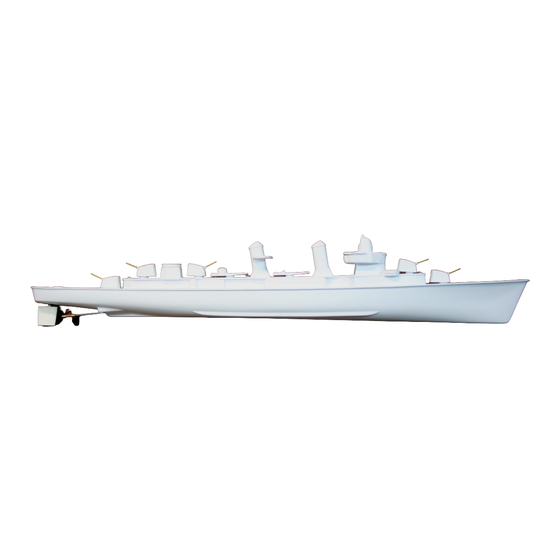
1:144 Scale Model RC Fletcher Class Destroyer Hull Kit
Manufactured by Vac-U-Boat 1259 Humphries Rd. Conyers, GA 30012 philpace@vac-u-boat.com
This Vac-U-Fletcher Hull Kit Features: Tough high-impact polystyrene hull, a scale deck
with realistic details including five 5-inch cannons with brass barrels, stacks with searchlight
platform, two torpedo launchers and the bridge with gun director overhead. The rudder kit
includes a rudder cast on a brass shaft with a self-aligning rudder bracket, rudder arm, stainless
steel pushrod, and e-z connector with stainless screw. The single drive kit includes a "365" motor
direct-driving the precision 1/8-inch stainless steel shaft supported by Oilite
stern tube with a brass coupling, injection-molded copper colored 1-inch polyethylene prop, 6-32
threaded drive dog, prop nut, six magnets to attach the 2nd deck and a motor mount that also holds
the included mini servo for the rudder. Once assembled, the hull is sealed up to the top of the deck
house. Although not necessary for most water conditions, the upper deckhouse openings can be
taped over with a strip of clear packing tape to completely waterproof the hull. Screws for the
motor, rudder pushrod & servo are accessible from openings in the top of the deck house for any
repair or maintenance. A more expensive twin counter-rotating drive kit is available to make the
model's drive the same as the real ship but isn't necessary as both single and twin drive setups will
drive and maneuver the ship at faster-than-scale speeds.
If you are looking for a museum-quality scale Fletcher-Class destroyer with hundreds of parts
and fine detail, DO NOT BUY THIS MODEL! This is a vacuum-formed plastic kit which
includes only the larger details of the real ship with adjustments made so the shape is compatible
with vacuum-forming equipment. Once assembled & painted and you have added your radio gear,
battery, electronic speed control, ballast weights & wiring connectors, it will run and look great in
the water. If you need additional details, they can be scratch built or 3D printed.
The boat can be painted with plastic-compatible hobby spray paints. Use ONLY plastic-safe
paints like Hobby Enamels, Krylon Fusion or Rustoleum American Accents 2X Ultra Cover
paints are the best. Sprayed or brushed acrylics work well too.
Please read the following information, warnings, tips and tricks before building this model.
Use caution with glue, the plastic bags, and small parts if children are around. Read the labels of
all adhesives, paints, and electronics purchased for this hull. Use extreme care with hobby knives
when cutting plastic.
Remember to turn on the transmitter first, then the boat's receiver. Teach your child to turn off
the boat before lifting it out of the water. Even a plastic prop can be hazardous to their little
fingers.
Enjoy your Vac-U-Fletcher. If you have any questions, you can contact me at philpace@vac-u-
boat.com.
Vac-U-Fletcher
™
®
bushings in the brass
© 2018 Philip Pace dba Vac-U-Boat™
Advertisement

Related Manuals for Vac-U-Boat Vac-U-Fletcher


Summary of Contents for Vac-U-Boat Vac-U-Fletcher
- Page 1 Even a plastic prop can be hazardous to their little fingers. Enjoy your Vac-U-Fletcher. If you have any questions, you can contact me at philpace@vac-u- boat.com. © 2018 Philip Pace dba Vac-U-Boat™...
- Page 2 If you bought this direct from Vac-U-Boat, I’ll reimburse you for standard return shipping. If you need some help, find a local boat club to join, check with the hobby shop where you purchased your motor and radio gear, or contact internet clubs and organizations for assistance.
-
Page 3: Kit Contents
KIT CONTENTS Available as a Hull Kit with Single Drive or optional counter-rotating Dual Drive. Hull pre-trimmed with the shaft journal pre-drilled for the stern tube. Pre-Trimmed Deck with recessed hatch openings ready to cut open in the deckhouse. 2nd Deck & Deck Components all of the deck bits needed for a great look. - Page 4 INSTRUCTIONS We are ready to get started building this Scale Fletcher hull kit. Follow the photos and captions to assemble your boat. Read through the instructions before building. Assemble the necessary tools and adhesives on a clean workbench or table. Keep paper towels handy to catch spills. Don’t forget the safety glasses! To build this kit you will need: A variable-speed drill.
- Page 5 SANDING BLOCK Held upright, the pre-trimmed edge of the hull does not have a flat top. It is raised and flared outward. The cross- section of the hull looks like this. Using the sanding block to span the width of the hull, sand off only the raised area leaving the flare curve to make a flat surface to glue to the deck.
- Page 6 Use a 3/16 inch drill to drill into the center of the rudder inset at the stern of the hull. Wallow out the hole a little so the rudder base (black aluminum rivet) will fit. Sand the rudder mount recess in the hull and sand inside the hull at the rudder mount as well.
- Page 7 5-Inch guns and their bases go together with the 2-piece barrels to make five guns for the deck. The bridge assembly starts with the bridge, formed upside-down where the pilot house crew can walk outside. The pilot house roof supports the mast and gun director. The pilot house is also formed upside-down. These parts stack together on top of the upper deck.
- Page 8 These half-round items are anti-aircraft gun placements near the Bow. Early Fletchers had an AA gun mount with a rangefinder mount next to it. Later versions had just the gun mount. The circle forms the floor of the early AA gun mount. The rectangles are bases for mounting the torpedo launchers.
- Page 9 Laying the upper blade flat against the side of the cannon, trim each side until it looks like this. Sand on the sanding block. Rotate it frequently to keep the base of the gun square and even on all sides. Sand just until the rounded bottom is gone as shown on the right photo, “after”...
- Page 10 Lightly sand inside the bottom of the gun shell. Apply super glue around inside the shell and spread evenly. Set the base on a flat scrap surface. Align the gun and press down to engage the base and hold for 10 seconds. It should look like this.
- Page 11 Locate the torpedo launchers. Outline the launcher with a pencil. Cut out the launcher along the line. Sand the edges straight. Cut out the two plastic rectangles. Sand smooth the bottom of the trimmed edges. Sand one side of a rectangle. Sand the underside of the launcher. Apply CA to the raised areas under the launcher. Press the sanded side of the rectangle to the underside of the launcher.
- Page 12 Sanded pair of stack halves “before” & “after”. Once done, hold together and tape one edge to make a hinge. Apply a thin layer of CA around the edge of one of the halves. Fold together and align. The CA will let you reposition the halves until you have them aligned.
- Page 13 Trim the outside with scissors. Use a knife to score the inside opening. Break open along the score lines. Cut around the outside along the line. Make a “tape handle” and sand the top and side opening smooth and straight. Scuff the bottom of the gun placements and the corresponding round areas of the upper deck and glue with CA.
- Page 14 Even the edges. Sand the bottom of the bridge roof. Sand the gun director. Rotate it frequently to sand evenly. Sand just until the rounded edge is gone. Same for the pilot house and the Bridge. Lightly dragging the blade sideways will remove rough edges left from sanding. Score the inside marks at the bridge.
- Page 15 The upper deck sits on top of the deck. It has a raised outline. Mark the bottom of the outline with a pencil and use your knife to lightly score the outline first, then repeat scoring until the edges will break away. Careful not to tear the upper deck at corners.
- Page 16 Set the motor fully into the motor mount recess as shown. Attach the motor bracket with the two screws provided. Do not overtighten. Leave the bracket as level as possible. Identify the + positive and - negative terminals. Attach your red (+) and black (-) wires to the motor by first “tinning” the motor tabs with solder, then tin the wire ends.
- Page 17 Insert the prop shaft into the stern tube and through the hull temporarily attaching the prop shaft to the motor assembly. Measure about 1/8” between the shaft and the rudder. Mark the position of the motor mount in the hull. Disconnect the shaft from the motor coupling.
- Page 18 While holding up the stern tube, force filled-epoxy under it into the recess. Lay the shaft down into it and add more epoxy on top. Make sure the stern tube is still sticking through the hull. Add filled epoxy to the motor mount. Don’t put any epoxy under the servo. Put epoxy into the hull at the marked motor location.
- Page 19 Before attaching the servo arm to the servo, we need to Centering the Servo “Center” the servo. This can be done with a Servo Tester or by connecting it to your radio system and powering it up. Connect the servo lead to the #1 channel of your receiver. Turn on your transmitter.
- Page 20 Turn the rudder servo left and right checking for uniform travel of the rudder and to ensure there is no binding of the rudder linkage. Run the motor. Check that all screws are tight. Don’t overtighten the rudder arm set screw. Remove the electronics.
- Page 21 Trace the inside of the three deck house hatches with a pencil to mark the trim lines. Slowly drill the corners with a 3/16 inch drill. Use a hobby knife or box cutter to score the lines until the hatches are open. Looks like this when done.
- Page 22 Find two scraps of wood or anything wider than the hull and taller than the deck cabin to hold the deck level while gluing it. Turn over the deck. Test fit the hull. The edge of the hull fits just inside the deck recessed edge. Set the deck upright on the sticks.
- Page 23 The bridge mounts to this upper deck structure with the rounded fronts even and the rear square to the corners of the upper deck below it. Scuff. Apply CA to one surface, press and hold. A mast can be installed for flags. Drill through the roof hole to the upper deck.
- Page 24 Get the cured stacks and the searchlight mount. Sand off the rounded edges of the bottom of the Stacks. Lightly sand, rotating the stack often so it will remain square. Sanded “before” & “after”. It is a good idea to put a scrap of foam inside the stacks for flotation.
- Page 25 It should last for years without changing. Before running: Put a droplet of sewing machine oil on the prop shaft where it exits the stern tube for lubrication. Wipe away the excess oil. Copyright © 2018 Philip Pace, d.b.a. Vac-U-Boat...
Need help?
Do you have a question about the Vac-U-Fletcher and is the answer not in the manual?
Questions and answers