Advertisement
Quick Links
NOTE:
Please read all
instructions carefully
before using this product
Table of Contents
Safety Notice
Hardware Identifier
Assembly Instruction
Exploded Diagram
Parts List
Warranty
Ordering Parts
Model
CB-610
Retain This
Manual for
Reference
11-20-07
OWNER'S
MANUAL
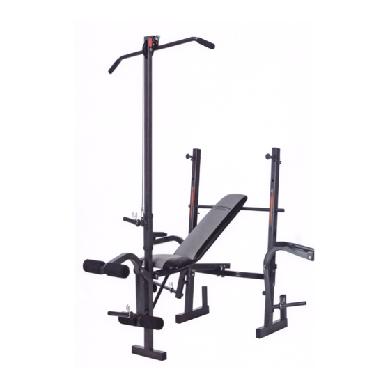
COMPETITOR
CB-610 STANDARD BENCH
14777 Don Julian Rd., City of Industry, CA 91746
Tel: (800) 999-8899 Fax (626) 961-9966
www.impex-fitness.com
info@impex-fitness.com
®
IMPEX
INC.
Advertisement

Related Manuals for Impex COMPETITOR CB-610


Summary of Contents for Impex COMPETITOR CB-610
- Page 1 Hardware Identifier Assembly Instruction Exploded Diagram Parts List Warranty Ordering Parts Model CB-610 Retain This Manual for Reference 11-20-07 OWNER'S ® IMPEX INC. MANUAL 14777 Don Julian Rd., City of Industry, CA 91746 Tel: (800) 999-8899 Fax (626) 961-9966 www.impex-fitness.com info@impex-fitness.com...
-
Page 2: Table Of Contents
ASSEMBLY INSTRUCTIONS..................EXPLODED DIAGRAM....................PARTS LIST......................…. WARRANTY......................…. ORDERING PARTS....................…. BEFORE YOU BEGIN Thank you for selecting the COMPETITOR CB-610 STANDARD BENCH by ® IMPEX INC. For your safety and benefit, read this manual carefully before using the machine. As a manufacturer, we are committed to provide you complete customer satisfaction. -
Page 3: Important Safety Notice
PHYSICIAN. THIS IS ESPECIALLY IMPORTANT FOR INDIVIDUALS OVER THE AGE OF 35 OR PERSONS WITH PRE-EXISTING HEALTH PROBLEMS. READ ALL INSTRUCTIONS BEFORE USING ANY FITNESS EQUIPMENT. IMPEX INC. ASSUMES NO RESPONSIBILITY FOR PERSONAL INJURY OR PROPERTY DAMAGE SUSTAINED BY OR THROUGH THE USE OF THIS PRODUCT. - Page 4 WARNING LABEL REPLACEMENT The Warning Label shown here has been placed on the Cross Brace. If the label is missing or illegible, please call customer service at 1-800-999-8899 for replacement. Apply the label in location shown.
-
Page 5: Hardware Identifier
HARDWARE PACK NOTE: The following parts are not drawn to scale. Please use your own ruler or scale to measure the size. -
Page 6: Assembly Instructions
ASSEMBLY INSTRUCTION Tools required assembling the machine: Two Adjustable Wrenches and Allen Wrenches STEP 1 (See Diagram 1) A.) Connect the Right Rear Upright Beam (#1) and Left Rear Upright Beam (#59) by a Cross Brace (#11) in the Mid-span. Secure them with two M10 x 2 3/8”... - Page 7 STEP 2 (See Diagram 2) A.) Connect the Front Stabilizer (#42) to the Main Seat Support (#52). Secure them with two M10 x ¾” Hex Bolts (#46), four ∅ ¾” Washers (#3), and two M10 Aircraft Nuts (#4). DO NOT tighten the nuts and bolts yet. Thread the Knob Bolt (#47) into the nut on the Front Stabilizer.
- Page 8 STEP 3 (See Diagram 3) A.) Slide a ∅ ¾” Washer (#3) onto a M10 x 5 ½” Hex Bolt (#54). Insert the Bolt through the Butterfly (#17). Place a M10 Regular Nut (#57) onto the Bolt. Then insert the Bolt through the hole on the Rear Upright Beam (#1).
- Page 9 STEP 4 (See Diagram 4) A.) Attach the hole-side of the Backrest Supports (#22) onto both ends of the Pivot on the Main Seat Support (#52). The other side rest against the Backrest Adjustment Bar (#10). B.) Place the Backrest Board (#18) onto the Backrest Supports. Secure it with four M6 x 1 ½”...
- Page 10 STEP 5 (See Diagram 5) A.) Attach the ball end of the Cable (#27) to the Pulley (#28). Place the Pulley in the open slot on the Lat Bar Frame (#31). Secure it with one M10 x 2 1/8” Hex Bolt (#32), two Pulley Bushings (#29), two ∅...
- Page 11 STEP 6 (See Diagram 6) A.) To store the bench in a vertical position, remove the Lat Bar Frame from the bench and place it onto the storage post on the Rear Upright Beam. B.) Pull out the 3” Short Lock Pin (#58) on the Main Seat Support to fold up the bench. Make sure to re-insert the Lock Pin on the bracket to secure the frame at the vertical position.
-
Page 13: Parts List
PARTS LIST KEY NO. DESCRIPTION QUANTITY Right Rear Upright Beam M10 x 2 3/8” Hex Bolt ∅ ¾” Washer M10 Aircraft Nut 1 5/8” x 2 3/8” End Cap 1 ¼” Square End Cap Bracket Lock Knob ∅ 1” Round End Cap Backrest Adjustment Bar Cross Brace ∅... -
Page 14: Warranty
No other warranty beyond that specifically set forth above is authorized by IMPEX. IMPEX is not responsible or liable for indirect, special or consequential damages arising out of or in connection with the use or performance of the product or other damages with respect to any economic loss, loss of property, loss of revenues or profits, loss of enjoyments or use, costs of removal, installation or other consequential damages or whatsoever natures.
Need help?
Do you have a question about the COMPETITOR CB-610 and is the answer not in the manual?
Questions and answers